Analog audio signal enhancement system using a noise suppression algorithm

a technology of noise suppression and analog audio, applied in the field of signal processing, can solve the problems of low power consumption of a/d converters, low noise suppression, and low system design time, and achieve the effect of suppressing noise, low power consumption, and suppressing nois

Inactive Publication Date: 2009-09-15
GEORGIA TECH RES CORP
View PDF14 Cites 11 Cited by
  • Summary
  • Abstract
  • Description
  • Claims
  • Application Information

AI Technical Summary

Benefits of technology

[0012]The present invention can also be viewed as providing methods for suppressing noise in an analog signal in continuous time. In this regard, one embodiment of such a method, among others, can be broadly summarized by the following steps: separating an input analog signal into sub-band analog signals; determining a gain for each sub-band signal that shall suppress the noise for that sub-band signal; and applying the gain to each sub-band signal to suppress the noise. In preferred embodiments, the steps are implemented using VLSI circuitry, such as floating gate technology. Because the method involves analog processing rather than digital, benefits from its implementation are extremely low power consumption and real time computation.

Problems solved by technology

Second, the system demands on current systems require very high resolution / high performance analog to digital (A / D) converters.
Therefore, the resulting A / D converter block is often consuming a large fraction of the power budget, as well as system design time.
Scaling will not help much in this case, since resolution has been increasing at approximately 1.5 bits / 5 years at the same performance, and quickly running into additional physical limits which might further slow this progress.
For example, Adaptive Wiener filtering typically requires extensive computation time on current microprocessors which requires a lot of power (e.g., 4 million instructions per second).
Thus, a heretofore unaddressed need exists in the industry to address the aforementioned deficiencies and inadequacies.

Method used


Image

  • Analog audio signal enhancement system using a noise suppression algorithm
  • Analog audio signal enhancement system using a noise suppression algorithm
  • Analog audio signal enhancement system using a noise suppression algorithm

Examples


Embodiment Construction

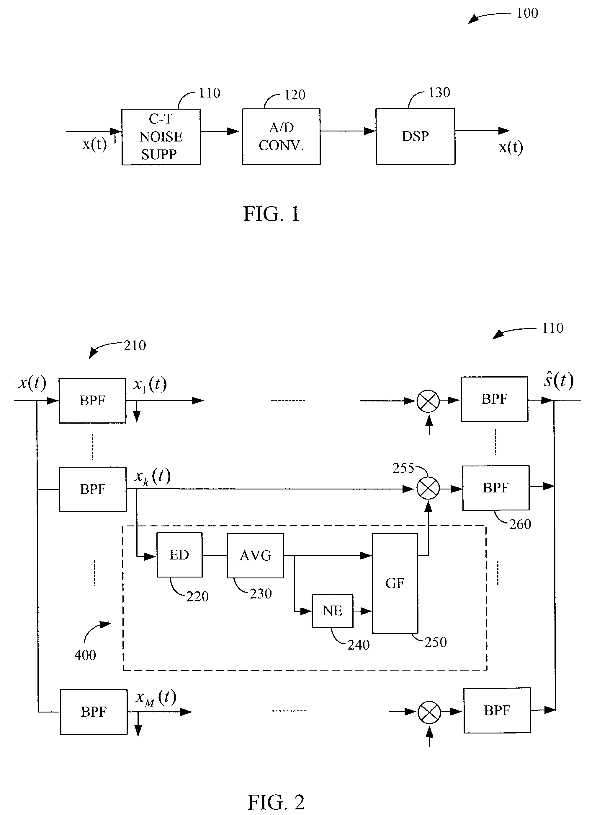
[0028]While most noise suppression techniques focus on the processing of discrete-time audio signals, FIG. 1 presents a cooperative signal processing system 100 in which the processing is performed on an analog audio signal prior to the analog / digital (A / D) conversion. By performing this significant portion of the processing in low-power analog circuits, the overall functionality of the system 100 is enhanced by utilizing analog / digital computation in a mutually beneficial way.

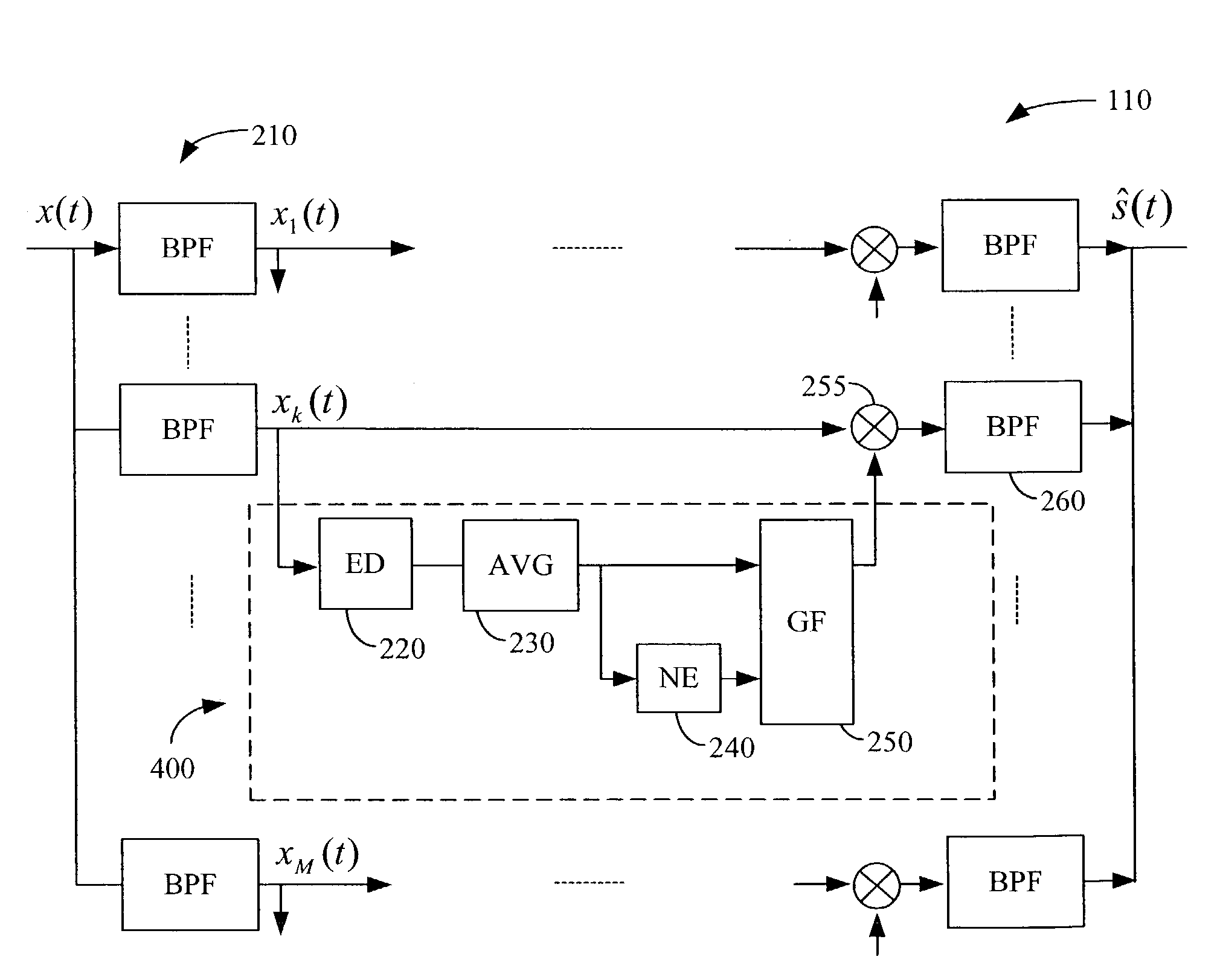
[0029]As shown in FIG. 1, the cooperative signal processing system 100 includes a continuous-time noise suppression system 110. The continuous-time noise suppression system 110 suppresses the noise evident in an analog signal x(t), such as an output of a microphone, before the analog signal x(t) undergoes analog to digital (A / D) conversion by an A / D converter 120. By performing analog signal processing on the signal x(t) before it is converted to digital, the computation load on a digital signal processor (DSP...


PUM


Abstract

One preferred embodiment of the present invention provides systems and methods for removing noise from an input analog signal in continues time. Briefly described in architecture, one embodiment of the system, among others, can be implemented as follows. An analog filtering system including VLSI circuitry separates an analog input signal into a plurality of sub-band signals. Then, an analog gain system including VLSI circuitry calculates a gain for each sub-band signal that suppresses the noise within the sub-band signal. In some preferred embodiments, VLSI circuitry includes floating gate technology. Methods and other systems are also provided.

Description

CROSS-REFERENCE TO RELATED APPLICATION[0001]This application claims priority to copending U.S. provisional applications entitled, “A Continuous-Time Speech Enhancement System in CMOS Using a Noise Suppression Algorithm,” having Ser. No. 60 / 367,058, filed Mar. 22, 2002, which is entirely incorporated herein by reference, and “Capacitively-Coupled Current Conveyer Second-Order Section,” having Ser. No. 60 / 367,066, filed Mar. 22, 2002, which is entirely incorporated herein by reference.TECHNICAL FIELD[0002]The present invention is generally related to signal processing and, more particularly, is related to noise suppression.BACKGROUND OF THE INVENTION[0003]Audio signal enhancement by removing additive background noise from a corrupted noisy signal has recently received increased attention due to the prosperity of portable communication devices. Traditional methods of noise suppression include spectral subtraction, Wiener filtering, and a number of modifications on these methods that in...

Claims


Application Information

Patent Timeline
Patent Type & Authority Patents(United States)
IPC IPC(8): H04B15/00G10L19/02G10L21/02H03G5/16H03H21/00
CPCG10L21/0208H04B15/00H03G5/165H03H21/0001G10L19/0204G10L21/0232
Inventor ELLIS, RICHARD THOMPSONYOO, HEEJONGGRAHAM, DAVID WILSONHASLER, PAUL EDWARDANDERSON, DAVID V.
Owner GEORGIA TECH RES CORP
Why Eureka
Try Eureka