Heat pump/direct expansion heat pump heating, cooling, and dehumidification system

a heat pump and direct expansion technology, applied in the field of heat pump/direct expansion heat pump and dehumidification system, can solve the problems of only removing humidity, reducing comfort levels, and affecting the operation of heat pumps, so as to ensure the maximum refrigerant charge efficiency levels of operation and increase system operational capacity and/or efficiencies.

Inactive Publication Date: 2009-09-22
EARTH TO AIR SYST
View PDF22 Cites 62 Cited by
  • Summary
  • Abstract
  • Description
  • Claims
  • Application Information

AI Technical Summary

Benefits of technology

[0026]It is an object of the present invention to disclose a means to utilize a three-mode receiver in a heat pump heating/cooling/dehumidification system, and particularly in a DX System, so as to help ensure maximum refrigerant charge efficiency levels of operation in each individual operational mode. It is an additional object of the present invention to disclose a means as how to incorporate such a system, which utilizes two interior air heat exch...

Problems solved by technology

However, in the cooling mode of operation, a second consequence of the heat pump's operation occurs.
In many areas, excessive moisture can create health concerns, such as fostering molds and dust mites, as well as decreasing comfort levels.
However, historically, as explained, humidity is only removed when the heat pump's cooling system is operating.
Such continuous operation typically results in excessive cooling, to the point of being uncomfortably cold.
While one could continuously operate a small cooling system in an effort to continuously remove humidity, and engage a larger cooling system only w...

Method used


Image

  • Heat pump/direct expansion heat pump heating, cooling, and dehumidification system
  • Heat pump/direct expansion heat pump heating, cooling, and dehumidification system
  • Heat pump/direct expansion heat pump heating, cooling, and dehumidification system

Examples


Embodiment Construction

[0086]The following detailed description is of the best presently contemplated mode of carrying out the invention. The description is not intended in a limiting sense, and is made solely for the purpose of illustrating the general principles of the invention. The various features and advantages of the present invention may be more readily understood with reference to the following detailed description taken in conjunction with the accompanying drawings.

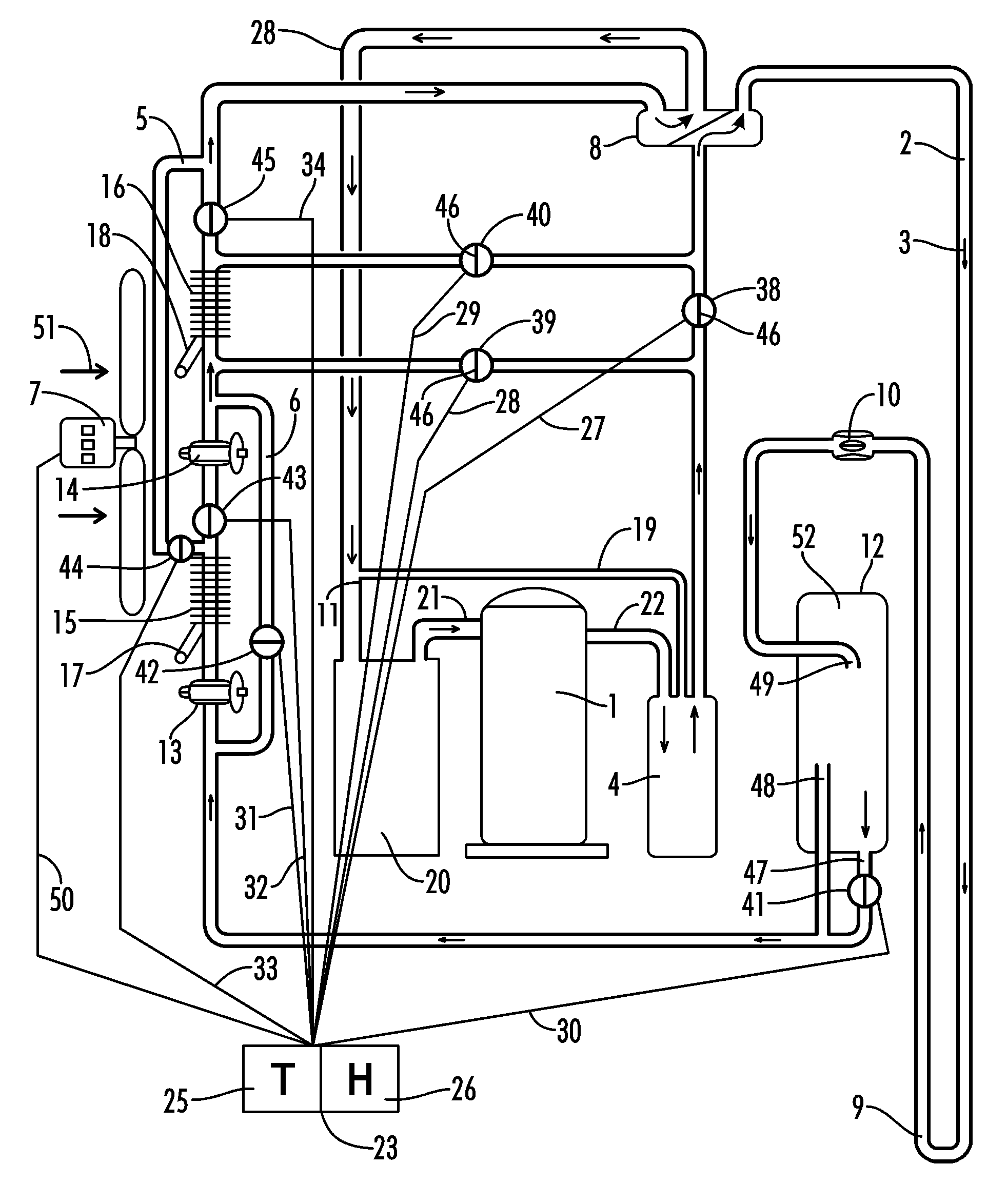
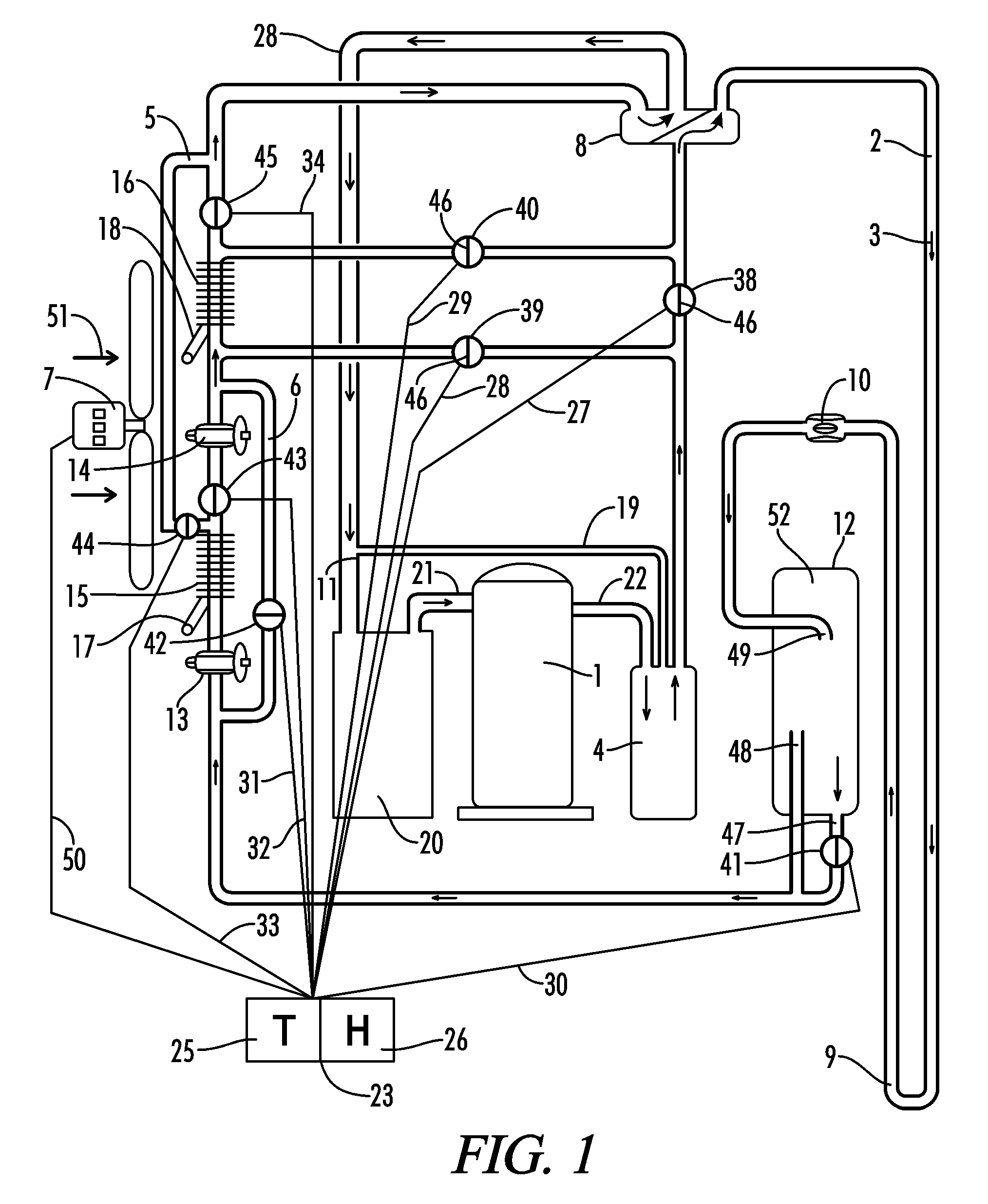
[0087]Referring now to the drawings in detail, where like numerals refer to like parts or elements, there is shown in FIG. 1 a side view of a simple version of a Deep Well Direct exchange (“DWDX”) geothermal heat pump system, operating in a cooling mode.

[0088]A refrigerant fluid (not shown) is transported, by means of a compressor's 1 force and suction, throughout the system and to / from various system components by means of refrigerant transport tubing 2. The directional flow of the refrigerant fluid within the refrigerant transport t...


PUM


Abstract

A heat pump heat pump system, operating with an R-410A refrigerant, comprised of at least one of an air source heat pump system, a water source heat pump system, and a direct expansion heat pump system, preferably for use in a Deep Well Direct Expansion heat pump system, which incorporates a three-mode receiver and an interior air handler, with at least one fan, with such air handler comprised of a combination of two sets of refrigerant to air heat exchange tubing/interior air heat exchange means, with by-pass lines and solenoid valves to facilitate system operation in the desired operational mode, all enabling optimum system performance in one of the desired heating mode, cooling mode, and dehumidification mode of system operation, as controlled by at least one of a thermostat/humidistat.

Description

[0001]This application claims priority to U.S. Provisional Patent Application Ser. No. 60 / 547,979 filed Feb. 26, 2004, entitled “Deep Well Direct Expansion System Dehumidifier”, and is a continuation-in-part of U.S. patent application Ser. No. 10 / 815,530 filed Apr. 1, 2004 now U.S. Pat. No. 7,191,604, entitled “Heat Pump Dehumidification System” both of which are hereby incorporated by reference in their entirety. All patents, patent applications and publication disclosed or discussed herein are hereby incorporated by reference in their entirety.[0002]A portion of the disclosure of this patent document contains material that is subject to copyright protection. The copyright owner has no objection to the facsimile reproduction by anyone of the patent document or the patent disclosure, as it appears in the Patent and Trademark Office patent file or records, but otherwise reserves all copyright rights whatsoever.BACKGROUND OF THE INVENTION[0003]The present invention relates to an impro...

Claims


Application Information

Patent Timeline
IPC IPC(8): F25B13/00F25B39/04F25B49/00F25D17/04
CPCF24F3/14F24F3/153F25B13/00F25B30/06F25B40/04F25B2313/002Y02B30/741F25B2313/02741F25B2313/0293F25B2313/0294F25B2400/16F25B2600/0253F25B2313/0212Y02B30/70
Inventor WIGGS, B. RYLAND
Owner EARTH TO AIR SYST
Why Eureka
Try Eureka