
Self-triggering CMOS imaging array utilizing guard region structures as light detectors

a technology of cmos imaging array and guard region structure, which is applied in the direction of television system, radioation controlled device, instruments, etc., can solve the problems of inability to synchronize the existing millions of x-ray machines in dental facilities, inability to detect the detection of the patient, and inability to meet the needs of patients

Active Publication Date: 2009-09-22
BAE SYST IMAGING SOLUTIONS
View PDF1 Cites 19 Cited by
  • Summary
  • Abstract
  • Description
  • Claims
  • Application Information

AI Technical Summary

Benefits of technology

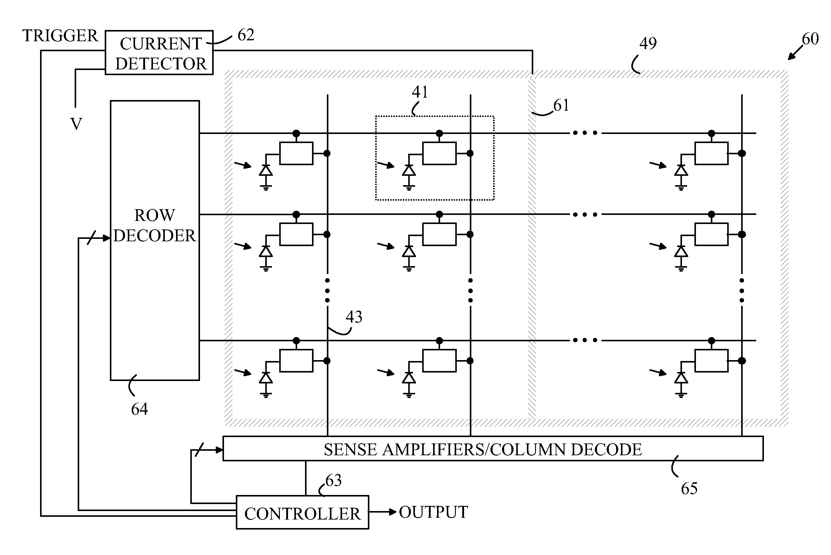
The present invention is a camera that can record images. It includes a camera sensor and separate circuitry for controlling the sensor. The camera has a region called a guard that separates the control circuitry from the sensor. The guard is exposed to light when the sensor is exposed to light. The camera has a current detector that measures the current flowing from the guard to a power rail. When the current exceeds a certain level, the detector triggers a start signal. This start signal resets the sensor and causes it to read the image. The guard region is made up of a specific type of semiconductor material. The invention allows for improved image quality and faster processing.

Problems solved by technology

Hence, conventional x-ray systems lack a synchronization system that can be used by the solid state image sensor.
Unfortunately, this strategy requires that the existing millions of x-ray machines already in place in dental facilities be modified at a considerable cost.
This type of system has three problems.
First, the area of the separate sensors is relatively small, and hence, the sensitivity of the detection is less than ideal.
The x-ray exposure during this detection time is wasted, and hence, the x-ray dose to which the patient is exposed is longer than necessary.
Second, the sensors do not sample the entire image, and hence, the triggering decision is made on data that is not necessarily representative of the image.
Providing a separate set of sensors with each imaging array increases the cost of the imaging system.
Unfortunately, this system has high power consumption due to the repeated readout cycles.
The high power consumption is particularly problematic in applications that rely on battery power.
Finally, this system does not detect the end of the x-ray exposure.

Method used


Image

  • Self-triggering CMOS imaging array utilizing guard region structures as light detectors
  • Self-triggering CMOS imaging array utilizing guard region structures as light detectors
  • Self-triggering CMOS imaging array utilizing guard region structures as light detectors

Examples


Embodiment Construction

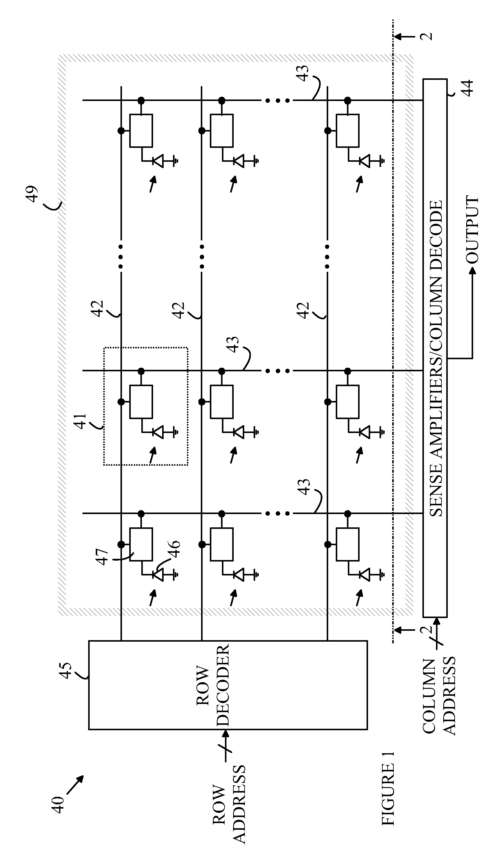
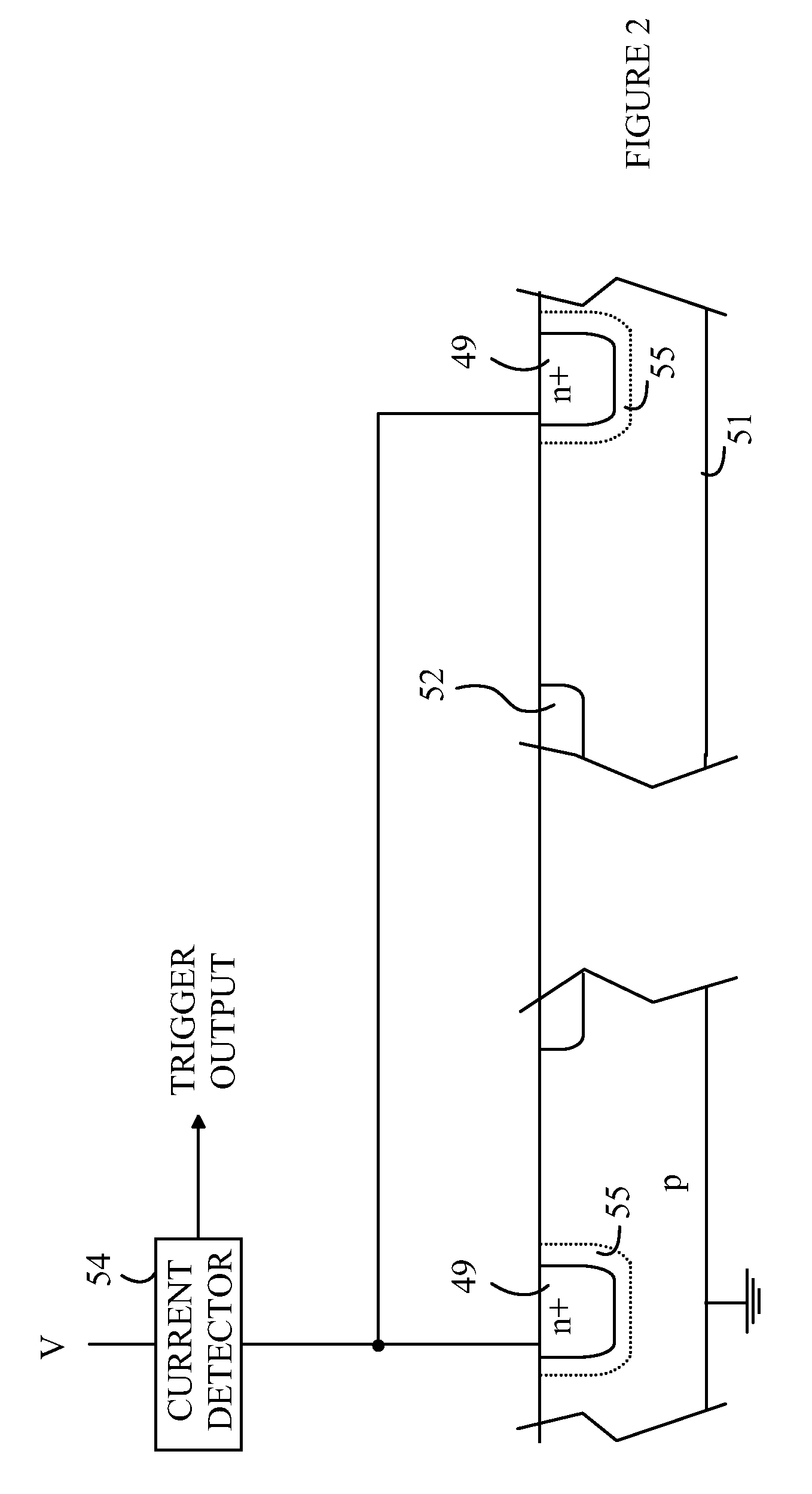
[0014]The manner in which the present invention provides its advantages can be more easily understood with reference to FIGS. 1 and 2, which illustrate a CMOS imaging array according to one embodiment of the present invention. FIG. 1 is a schematic view of the top surface of a die containing imaging array 40, and FIG. 2 is a cross-sectional view through line 2-2 shown in FIG. 1. Imaging array 40 is constructed from a rectangular array of pixel sensors 41. Each pixel sensor includes a photodiode 46 and an interface circuit 47. The details of the interface circuit depend on the particular pixel design. However, all of the pixel sensors include a gate that is connected to a row line 42. The gate is used to connect that pixel sensor to a corresponding bit line 43. In addition, most pixel sensors include a charge to voltage converting circuit that converts the charge stored by the photodiode during the image exposure to a voltage that is readout through the gate. The photodiodes accumula...


PUM


Abstract

A camera having an exposure detector is disclosed. The camera includes an array of pixel sensors, CMOS circuitry that is separate from the array of pixel sensors, a guard region, and a current detector. The guard region separates the CMOS circuitry from the array of pixel sensors. The guard region is positioned such that the guard region is exposed to light when the array of pixel sensors is exposed to light. The current detector measures the current flowing from the guard region to a power rail when the guard region is biased to a predetermined potential and generates a start trigger signal when the current exceeds a threshold value. A controller resets the pixel sensors in response to the start trigger signal.

Description

BACKGROUND OF THE INVENTION[0001]Solid state image sensors have replaced conventional film for capturing images in cameras. The image sensor typically includes a two-dimensional array of pixels. Each pixel includes a photodiode that records the light received at one point in the scene that is being recorded. To capture an image, each pixel is reset prior to the scene being imaged onto the sensor. After a predetermined exposure time, the charge stored by each photodiode is readout to provide an image of the scene.[0002]In a conventional camera, the exposure is controlled by a shutter that is triggered in response to the user pushing a button. The image sensor is reset just before the shutter opens and is readout at a predetermined time after the shutter closes. These operations are synchronized to the user pushing the button.[0003]In some applications, the imaging array must determine when the exposure begins and ends without the aid of a synchronization signal such as the user pushi...

Claims


Application Information

Patent Timeline
Patent Type & Authority Patents(United States)
IPC IPC(8): H01L27/00H01L31/00
CPCH01L27/14643H01L27/1463
Inventor LIU, XINQIAO
Owner BAE SYST IMAGING SOLUTIONS
Learn More