Fluid heating apparatus

a technology of heating apparatus and fluid, which is applied in the direction of lighting and heating apparatus, heating types, air humidification systems, etc., can solve the problems of insufficient heating efficiency, complicated fin structure, and high cost, and achieve the effect of effective and uniform heating of fluid and reasonable cos

Active Publication Date: 2009-09-22
TOKYO ELECTRON LTD
View PDF11 Cites 24 Cited by
  • Summary
  • Abstract
  • Description
  • Claims
  • Application Information

AI Technical Summary

Benefits of technology

[0007]The present invention has been made in view of the forgoing problems, and therefore the main object of the present invention is to provide a fluid heating apparatus which is capable of effectively and uniformly heating a fluid, and which can be fabricated at a reasonable cost. Preferably, the fluid heating apparatus can heat any sort of fluid.
[0009]According to the present invention, the radiant-light-absorbing paint efficiently absorbs thermal radiation emitted from the heating lamp, the pipe is heated efficiently, and thus the fluid flowing through the pipe is heated efficiently through the heat transfer from the pipe to the fluid. The fluid is thus efficiently heated regardless of the sort of the fluid, or the thermal-radiation absorption of the fluid.
[0011]As the inner surface is formed of the chemical-resistant synthetic resin, a corrosive fluid can be heated without damaging the pipe. If the heat-conductive layer is provided, the heat generated in the radiant-light-absorbing paint due to the absorption of the thermal radiation is uniformly transferred to and distributed over the inner surface formed of the chemical-resistant synthetic resin through the heat-conductive layer, and thus the fluid can be heated uniformly, even if the inner surface is formed of the chemical-resistant synthetic resin having relatively low heat conductivity.
[0014]Due to the provision of the tubular container, dissipation of the thermal energy generated by the heating lamp can be suppressed, improving the heating efficiency. As the radiant light emitted from the heating lamp and leaked through gaps (if any) in the tubular structure is reflected by the light-reflective inner surface of the tubular container to fall on the outer surface of the tubular structure, the fluid can be heated more efficiently.
[0015]The fluid heating apparatus may further include an inert gas supply adapted to supply an inert gas into an interior of the tubular container. This configuration prevents penetration of external atmosphere into the tubular container, and achieves safer operation of the fluid heating apparatus.

Problems solved by technology

In general, a fluid heating apparatus of the foregoing direct-heating type has some problems.
First, if the thermal-radiation absorption of the fluid is high, the fluid flowing through an area, remote from the heating lamp, in the fluid-flowing space is not sufficiently heated, while the fluid flowing through an area, near the heating lamp, in the fluid-flowing space is efficiently heated.
Thus, sufficient heating efficiency can not be achieved.
The fin structure is complicated, and thus costly.
If the fluid to be heated is DHF, the quartz material contacting with the fluid will be dissolved therein, and thus cannot be used.

Method used


Image

  • Fluid heating apparatus
  • Fluid heating apparatus
  • Fluid heating apparatus

Examples


first embodiment

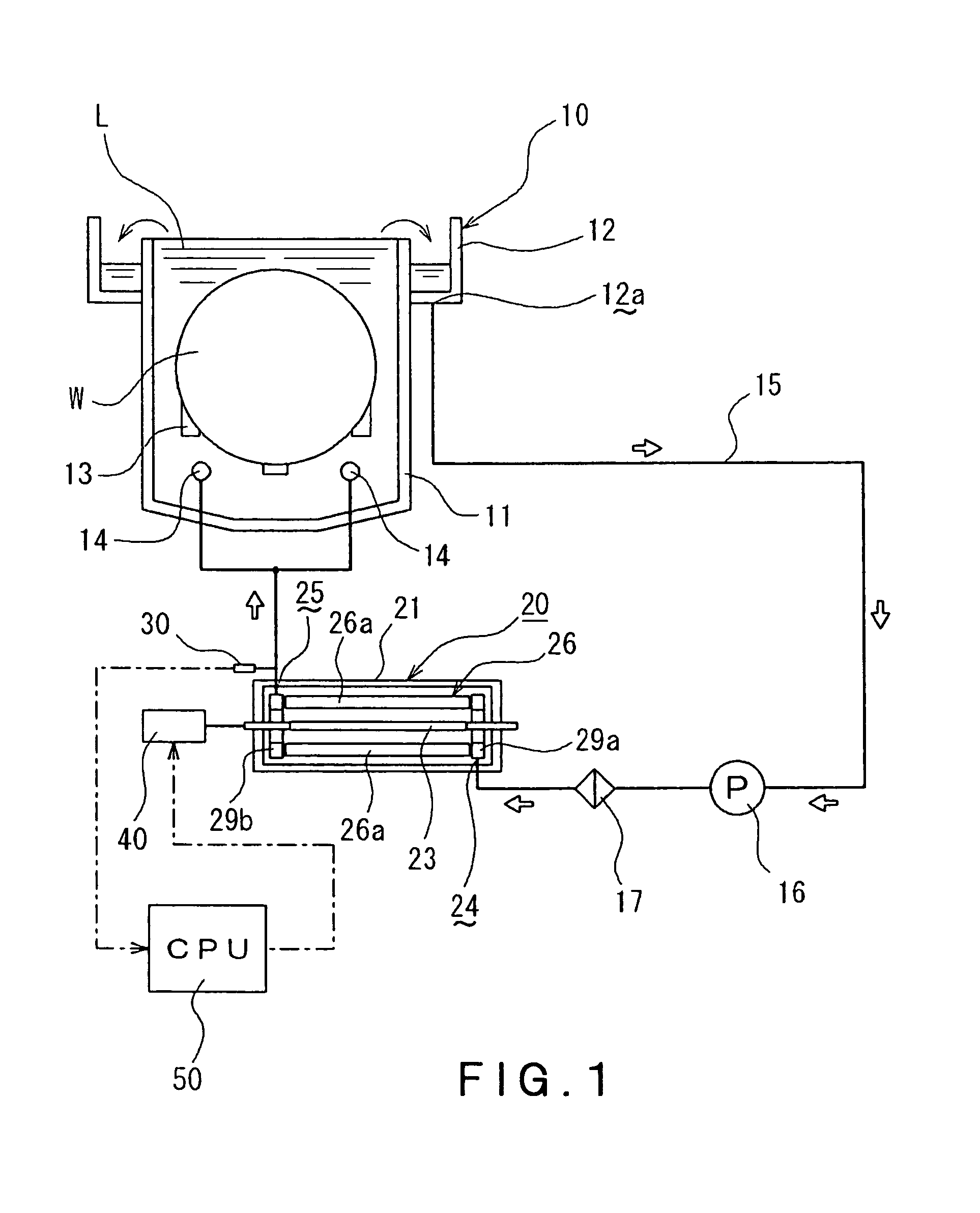
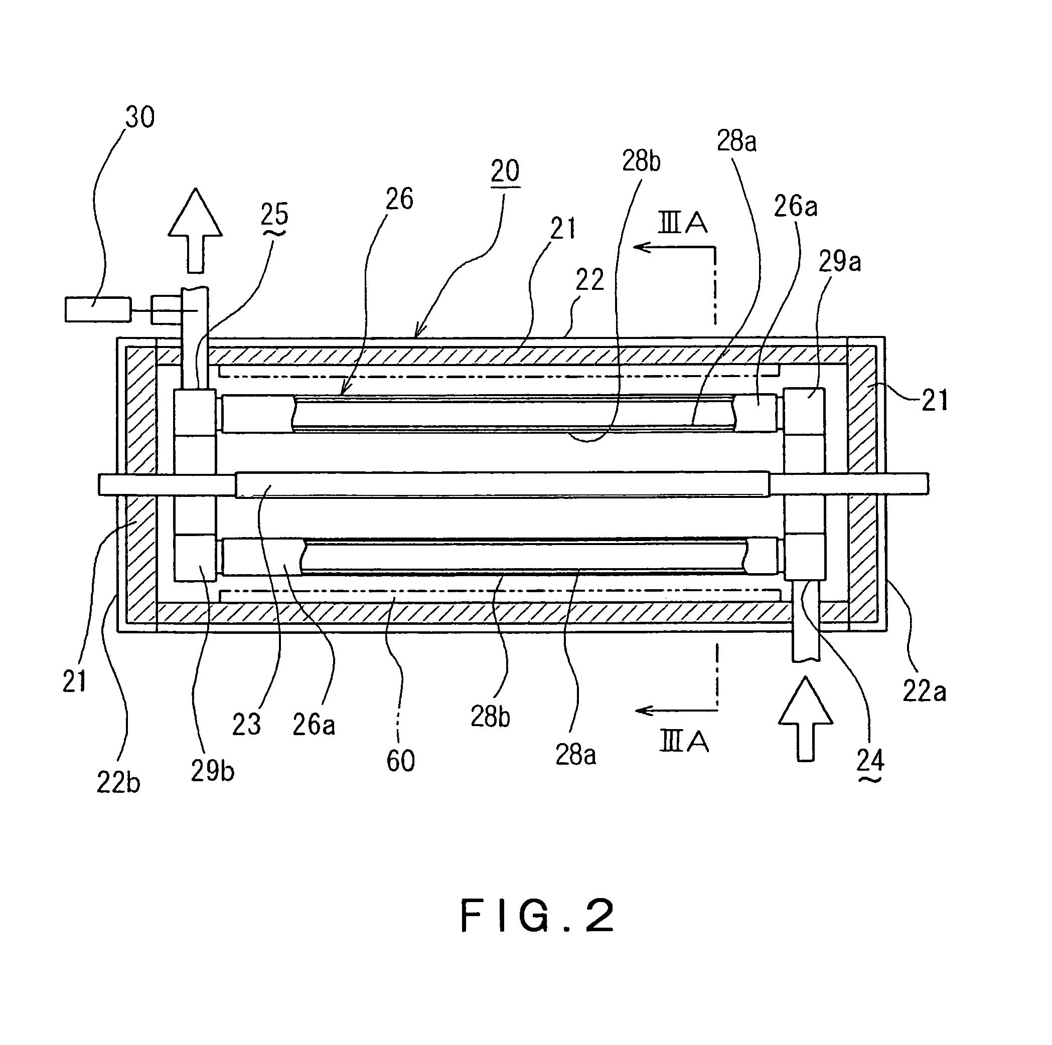
[0029]A fluid heating apparatus in a first embodiment of the present invention and a cleaning system equipped with the fluid heating apparatus will be described with reference to FIGS. 1, 2, 3A and 3B.

[0030]Referring to FIG. 1, the cleaning system includes: a cleaning tank 10 having an inner tank 11 that holds a cleaning liquid L, such as diluted hydrofluoric acid (DHF) or a rinse liquid (e.g., deionized water), and an outer tank 12 surrounding the upper opening of the inner tank 11 to receive the cleaning liquid overflowing from the inner tank 11; cleaning liquid supply nozzles 14 arranged at a lower area of the interior of the inner tank 11; a circulation passage 15 having a first end connected to the cleaning liquid supply nozzles 14 and a second end connected to a drain port 12a arranged at a bottom of the outer tank 12. A circulation pump 16, a filter 17 and a fluid heating apparatus 20 are arranged in the circulation passage 15 in that order from the drain-port 12a side. A waf...

second embodiment

[0039]The fluid heating apparatus in a second embodiment of the present invention will be described with reference to FIGS. 4A, 4B, 5A and 5B.

[0040]In the second embodiment of the fluid heating apparatus 20A, the tubular structure 26A comprises a single pipe 70, which is wound in a spiral configuration around the heating lamp 23 to be in a form of a tube. The tubular structure 26A surrounds the halogen lamp 23 with an annular gap being formed between the halogen lamp 23 and the tubular structure 26A. The spiral axis of the pipe 70 coincides with the longitudinal axis of the halogen lamp 23. In view of the heating efficiency, adjacent portions of the pipe 70 with respect to the spiral-axis direction are preferably in close contact with each other, but may be in close proximity while remaining a slight gap therebetween as long as leakage of radiant light emitted from the halogen lamp 23 to the exterior of the tubular structure 26A can be prevented or suppressed to a negligible level. ...

third embodiment

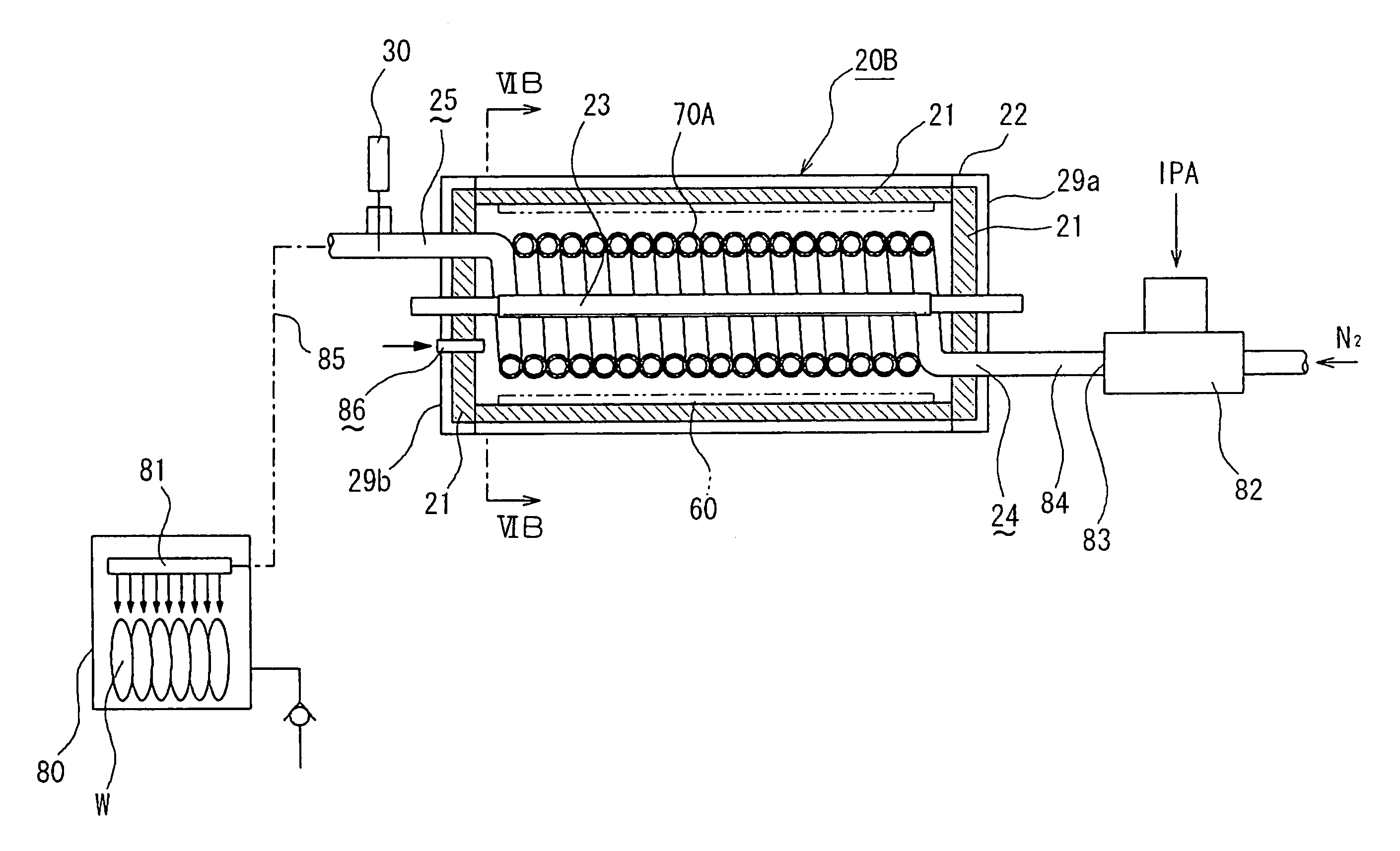
[0043]FIGS. 6A, 6B, 7A and 7B show an IPA drying system for drying semiconductor wafers by using a mixed gas of IPA vapor and N2 gas, which is equipped with a fluid heating apparatus 20B in the third embodiment of the present invention. The IPA drying system includes: a process container 80 adapted to accommodate semiconductor wafers W (i.e., process objects) therein; a fluid supply nozzle 81 for jetting a mixed gas of IPA vapor and N2 gas toward the semiconductor wafers W accommodated in the process container 80; a fluid heating apparatus 20B in a third embodiment according to the present invention; and a two-fluid nozzle 82 for atomizing IPA liquid by using N2 gas.

[0044]The fluid heating apparatus 20B in the third embodiment differs from the fluid heating apparatus 20A in the second embodiment only in the following respects.

[0045]First, the cross-sectional structure of the spiral pipe 70A of the fluid heating apparatus 20B is different from that of the spiral pipe 70 of the fluid ...


PUM

PropertyMeasurementUnit
temperatureaaaaaaaaaa
chemical-resistantaaaaaaaaaa
heat-conductiveaaaaaaaaaa

Abstract

Disclosed is a fluid heating apparatus including a halogen lamp 23, and a tubular structure 26 surrounding the heating lamp and having a fluid inlet 24 and a fluid outlet 25. The tubular structure 26 comprises plural straight pipes 26a arrayed circumferentially around the halogen lamp 26, with adjacent straight pipes 26a being in contact with each other, or being slightly spaced from each other. At least the surfaces, facing the halogen lamp 26, of the straight pipes 26a are coated with a black paint 27, or a radiant-light-absorbing paint.

Description

TECHNICAL FIELD[0001]The present invention relates to a fluid heating apparatus, and more specifically to a fluid heating apparatus that heats a flowing fluid by thermal radiation emitted from a heating lamp.BACKGROUND ART[0002]A semiconductor device fabricating process includes a fluid treatment that brings a process object, such as a semiconductor wafer, into contact with a processing fluid to treat the process object. In one example of the fluid treatment, the process object is immersed in a processing fluid, such as diluted hydrofluoric acid (DHF) or a rinse liquid, held in a cleaning tank in order to clean the process object. In another example of the fluid treatment, a mixed gaseous fluid of vaporized isopropyl alcohol (IPA) and nitrogen gas (N2 gas) is supplied to a process object to dry the same. In general, the temperature of the processing fluid must be regulated at a designated target temperature in order to achieve the desired process result. To this end, a fluid heating...

Claims


Application Information

Patent Timeline
Patent Type & Authority Patents(United States)
IPC IPC(8): F24F3/14H05B3/40
CPCF24H1/101F24H1/162F28F2245/06F28D7/10F28D7/02F28D7/00
Inventor KAMIKAWA, YUJINAKASHIMA, MIKIOTSUDA, OSAMU
Owner TOKYO ELECTRON LTD
Why Eureka
Try Eureka