Rapid spatial averaging over an extended sample in a Raman spectrometer

a raman spectrometer and spatial average technology, applied in the field of optical spectroscopy, can solve the problems of reducing the sensitivity of the instrument, the same drawback of defocusing, and the variable defocus mechanism varying the sensitivity, so as to reduce the degradation or burning of the sample, the effect of minimal loss of sensitivity and rapid spatial averaging

Active Publication Date: 2009-09-29
THERMO ELECTRON SCI INSTR
View PDF3 Cites 28 Cited by
  • Summary
  • Abstract
  • Description
  • Claims
  • Application Information

AI Technical Summary

Benefits of technology

[0011]In accordance with the present invention, an optical apparatus is utilized to provide rapid spatial averaging over a large sample area by utilizing configured X-Y scanning mirror(s) to provide for angular displacement and an objective lens configured to focus and spatially displace such angularly displaced radiation so as to induce a desired emission in a Raman spectrometer. The spatial averaging configurations disclosed herein also reduce sample degradation or burning resulting from the high intensity of the directed optical source. Moreover, the dimensions of the sample area of the spatial averaging are adjusted to match specific sampling requirements.
[0012]Another aspect of the present invention is directed to a Raman spatially averaging method that includes: providing drive signals in a prime ratio to at least one X-Y scanning mirror so that an angularly displaced beam of light from an illumination source can be produced; spatially displacing via a focusing objective lens, the angularly displaced illumination beam of light so that a desire

Problems solved by technology

These properties, while beneficial, cause a problem when attempting to characterize materials that are inhomogeneous, either in their composition, or in their surface properties.
However, defocusing the source and/or the spectrograph reduces the amount of light entering the spectrograph aperture, which thus degrades the sensitivity of the instrument.
Moreover, a variable defocus mechanism varies the sensitivity and often is complex as well as cost ineffective.
An alternate solution is to scramble the laser and spectrograph beams, for example, by using diffusers or mu

Method used


Image

  • Rapid spatial averaging over an extended sample in a Raman spectrometer
  • Rapid spatial averaging over an extended sample in a Raman spectrometer
  • Rapid spatial averaging over an extended sample in a Raman spectrometer

Examples


example experimental

Results:

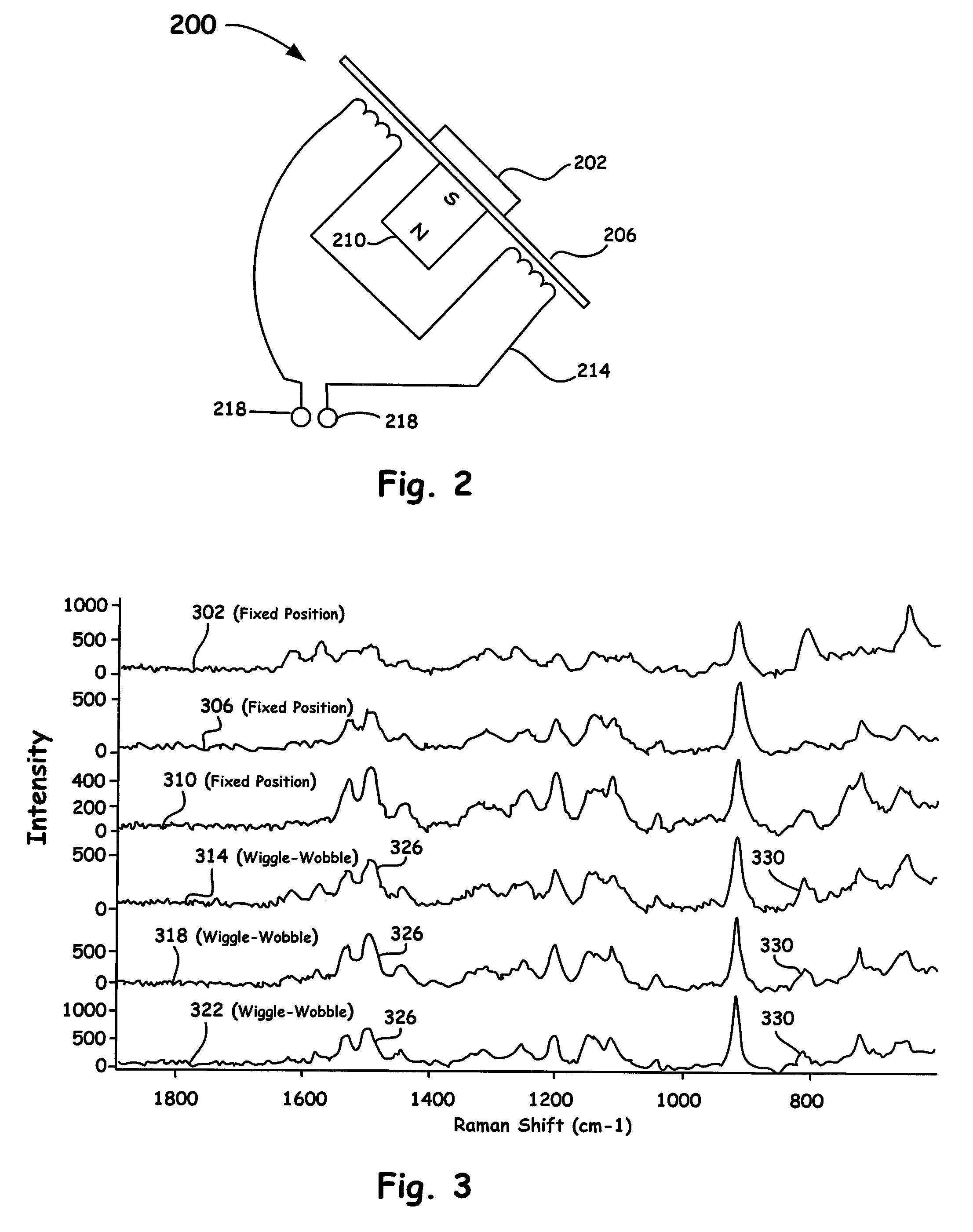
[0046]FIG. 3 shows example experimental Raman spectral data resulting from an interrogated orange Alka-Seltzer sample so as to demonstrate the concept of the invention. Thus, as shown in FIG. 3, the first three spectra, as denoted by the reference numerals 302, 306, and 310, are obtained by allowing the system to sit fixed at three different positions (i.e., non-scanned spectra). The second three spectra, as denoted by the reference numerals 314, 318, and 322, are obtained by scanning (using sine drive signals of about 60 Hz) the focused laser spot about a line displacement of up to about 5 mm via the moveable reflector, as shown in FIG. 2. As illustrated in FIG. 3, there are two distinct peaks of sufficient intensity at about 800 (as denoted by the reference numeral 330) and 1500 cm−1 (as denoted by the reference numeral 326) visible in the scanned spectra (i.e., the scanning test positions, 314, 318, and 322), which suggests the presence of two different compounds. However...


PUM


Abstract

An optical method and apparatus is utilized to provide rapid spatial averaging over a large sample area in a Raman spectrometer, without defocusing of the optical source or the collection optics. Spatial averaging provides a representative spectrum of a sample that is inhomogeneous, either in its composition or surface characteristics. The spatial averaging configurations and methods disclosed herein also reduce sample degradation or burning resulting from the high intensity of the directed optical source. Moreover, the dimensions of the sample area of the spatial averaging methods and configurations of the present invention are adjusted to match specific sampling requirements.

Description

BACKGROUND OF THE INVENTION[0001]1. Field of the Invention[0002]The present invention relates to optical spectroscopy. More particularly, the present invention relates to a dispersive Raman scanning method and apparatus for characterizing materials.[0003]2. Discussion of the Related Art[0004]When illuminating light, such as a laser beam, is incident upon a sample material, molecular bonds in the material can be excited by the incident light and can emit radiation which can be detected as scattered light. The Rayleigh component of the scattered light corresponds to the light emitted when the molecule relaxes from the excited state to the ground state. Infrequently, the molecule relaxes to a different vibrational or rotational level in the ground state. This produces Raman scattering components at Stokes and Anti-Stokes frequencies. A sample composed of multiple molecular species will produce a spectrum of such Raman scattering. The Raman scattering components can be detected and anal...

Claims


Application Information

Patent Timeline
IPC IPC(8): G01J3/44G01N21/65
CPCG01J3/02G01J3/44G01N21/65G01J3/0208G01N2021/656G01J3/021
Inventor DECK, FRANCIS J.
Owner THERMO ELECTRON SCI INSTR
Why Eureka
Try Eureka