Lens driving device

a driving device and lens technology, applied in piezoelectric/electrostrictive/magnetostrictive devices, mountings, instruments, etc., can solve the problems of degrading the device's characteristics, driving contacting parts with a rough surface, etc., and achieves stable operation characteristics and higher driving characteristics.

Inactive Publication Date: 2009-09-29
SAMSUNG ELECTRO MECHANICS CO LTD
View PDF8 Cites 20 Cited by
  • Summary
  • Abstract
  • Description
  • Claims
  • Application Information

AI Technical Summary

Benefits of technology

[0013]An aspect of the present invention provides a lens driving device which, during frictional driving, generates a sufficient friction force necessary for driving a lens, with predetermined hardness maintained, while suffering minimal abrasion even during long operation, thereby achieving stable operation characteristics and higher driving characteristics.

Problems solved by technology

However, when the vibrator runs for long time, the friction force between the guide shaft and the driving contacting part causes the driving contacting part having a very rough surface to be abraded even though the driving contacting part is formed of a high-hardness material such as alumina ceramics AlO2 or silicon carbide SiC.
Accordingly, foreign dusts from abrasion may infiltrate into sensitive parts to degrade characteristics of the device.

Method used


Image

  • Lens driving device
  • Lens driving device
  • Lens driving device

Examples


example

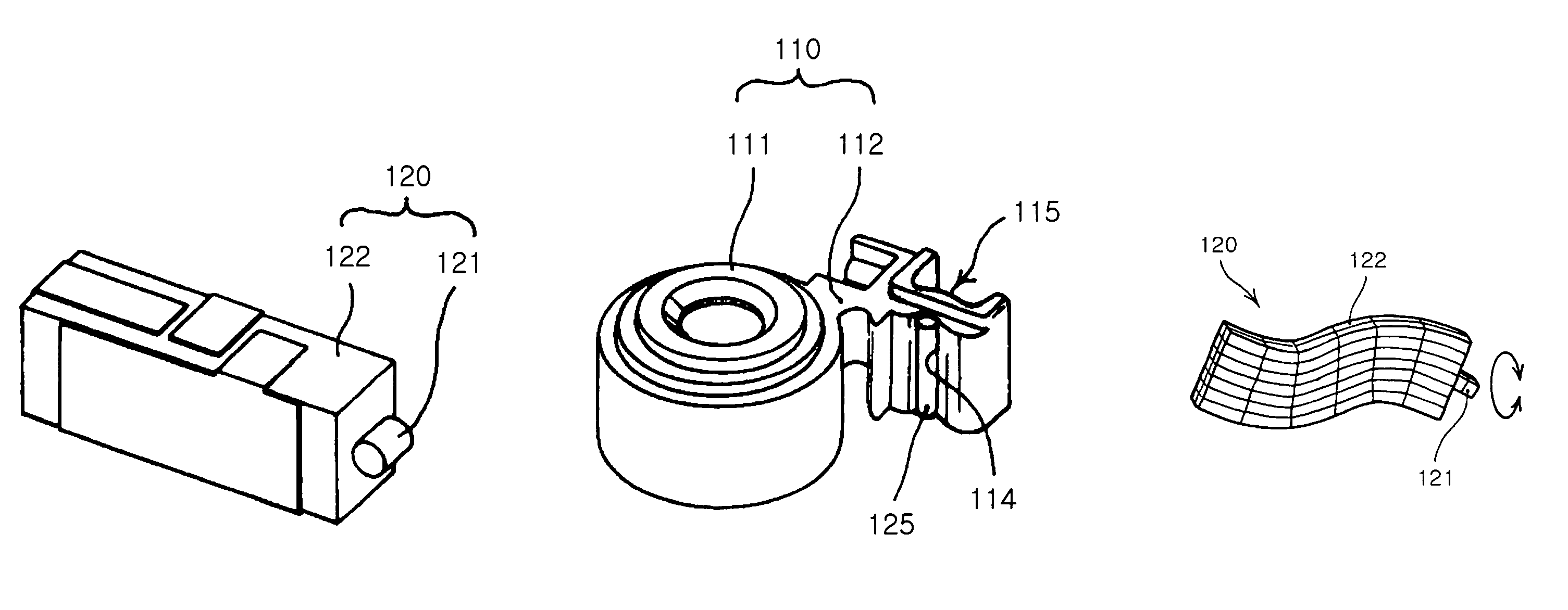
[0084]Table 2 below shows results after repeatedly operating an actuator 300,000 times, which employed the tip friction member 121 and the friction member 125 formed of high-strength friction materials of Table 1.

[0085]

TABLE 1FractureFrictionDensityHardnessstrengthTensilematerial(kg / mm3)(HK)(GPa)forceRemarkSiC32002480 kg / mm20.18620.03448~0.1379Al2O340002100 kg / mm20.9034 0.2552~0.2607Super-hard alloy158001875 kg / mm20.3838~0.57930.3448High speed steel1250 kg / mm20.44000.3800Corrosion

[0086]

TABLE 2Tip frictionFrictionComparison (after 300,000membermemberfrictional operations)1Al2O3Al2O3Degraded performance2Al2O3High-speedExcessive abrasion, greatsteel (SKH)amount of dusts, noises3SiCHigh-speedExcessive abrasion, greatsteel (SKH)amount of dusts4Super-Super-Good performance, smallhardnesshardnessamount of dustsalloy(WC)steel (SKH)5Super-Super-Good performance, smallhardnesshardnessamount of dustsalloy(WC)alloy (WC)

[0087]As noted in Table 2, when the tip friction member 121 and the friction...


PUM


Abstract

A lens driving device including: a lens barrel having at least one lens therein; an actuator having a tip friction member provided at a leading end of a body thereof to be in contact with a friction member of the lens barrel, the actuator being flexed and bent upon application of power to provide a driving force necessary for driving the lens barrel in an optical axis direction; a preload member compressing the actuator against the lens barrel to keep the friction member and the tip friction member in contact with each other; and a guiding part guiding the lens barrel to move in the optical axis direction, wherein the friction member and the tip friction member are formed of a super-hard alloy.

Description

CROSS-REFERENCE TO RELATED APPLICATIONS[0001]This application claims the priority of Korean Patent Application No. 2006-94351 filed on Sep. 27, 2006, in the Korean Intellectual Property Office, the disclosure of which is incorporated herein by reference.BACKGROUND OF THE INVENTION[0002]1. Field of the Invention[0003]The present invention relates to a lens driving device employed in an optical apparatus, more particularly, which, during frictional driving, generates a friction force necessary for driving a lens, with predetermined hardness maintained, but suffers minimal abrasion, thereby achieving stable operation properties and higher driving properties.[0004]2. Description of the Related Art[0005]In general, an optical apparatus includes a lens driving device for driving a lens using a cam structure, a screw or a piezoelectric element. The lens driving device employs a motor or the piezoelectric element to generate a driving force and the cam structure or the screw to transmit the...

Claims


Application Information

Patent Timeline
Patent Type & Authority Patents(United States)
IPC IPC(8): G02B7/02
CPCG02B7/021G02B7/08H02N2/026H02N2/004H01L41/0913H10N30/2023G02B7/04G02B7/02
Inventor LEE, DONG KYUNKANG, BYUNG WOO
Owner SAMSUNG ELECTRO MECHANICS CO LTD
Why Eureka
Try Eureka