
Methods and apparatus to prevent network mapping

a network mapping and network technology, applied in the field of methods and apparatus to prevent network mapping, can solve problems such as the inability to route non-looping packets, the inability to effectively solve the problem of loop routing performance degradation, and the inability to effectively route non-looping packets

Active Publication Date: 2009-09-29
CISCO TECH INC
View PDF7 Cites 34 Cited by
  • Summary
  • Abstract
  • Description
  • Claims
  • Application Information

AI Technical Summary

Benefits of technology

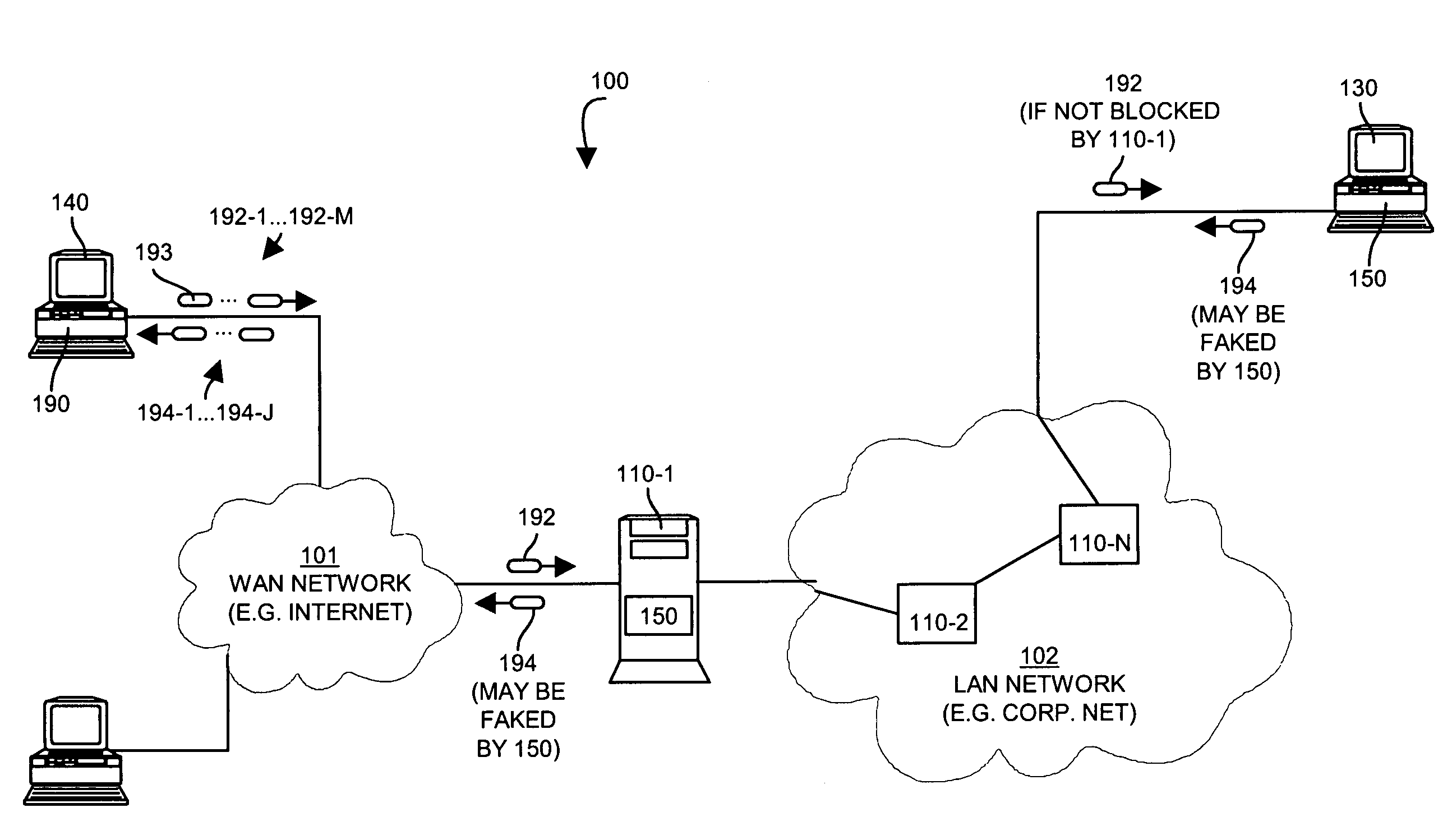
[0009]Also as noted above, a user operating trace route causes a series of packets to be sent onto the network towards a destination, each with a subsequently increasing time to live values. In response, the trace route process receives an error response from each network device in the network path that decrements the time to live field to zero within the series of packets sent, until a trace route packet with a sufficiently large time to live sent from trace route eventually reaches the intended destination or target address. While perimeter firewalls typically block trace route inbound packets with a time to live of 1, some malicious trace route scanners simply increment the time to live by one if no response is received, such that that the node does not drop the subsequent trace route packet, but only the one with the time to live of 1. This allows the malicious trace route program to complete mapping the network path and avoid being dropped.
[0011]In contrast, the present system disclosed herein prevents an attacker from using trace route to map an enterprise or other network. The solution disclosed herein involves detecting the situation of a process at a source address operating a trace route scan, associating a sequence of packets with an instance of the trace route scan, and using this information to modify security posture to either block incoming trace route packets with higher time to live values, or block responses, or provide misinformation in such responses to confuse the scanning entity. This solution is effective, for example, when both network devices (i.e., routers, switches) and end host systems implement this capability, however there is no interdependency which prevents this solution from functioning effectively when present only on one type of component (i.e. in hosts or in data communications devices).

Problems solved by technology

Over time, the number of packets traveling in this loop would accumulate to the point that the routers in the loop would suffer from performance degradation and become unable to route non-looping packets in a timely manner.
This solution is effective, for example, when both network devices (i.e., routers, switches) and end host systems implement this capability, however there is no interdependency which prevents this solution from functioning effectively when present only on one type of component (i.e. in hosts or in data communications devices).

Method used


Image

  • Methods and apparatus to prevent network mapping
  • Methods and apparatus to prevent network mapping
  • Methods and apparatus to prevent network mapping

Examples


Embodiment Construction

[0019]Embodiments disclosed herein provide a computerized device such as a data communications device (a router, switch or other such device) or a host computer system configured with a trace detector operable to detect and prevent trace route mapping of a network. Embodiments include the computerized device, as well as the trace detector itself such as may be embodied only in software.

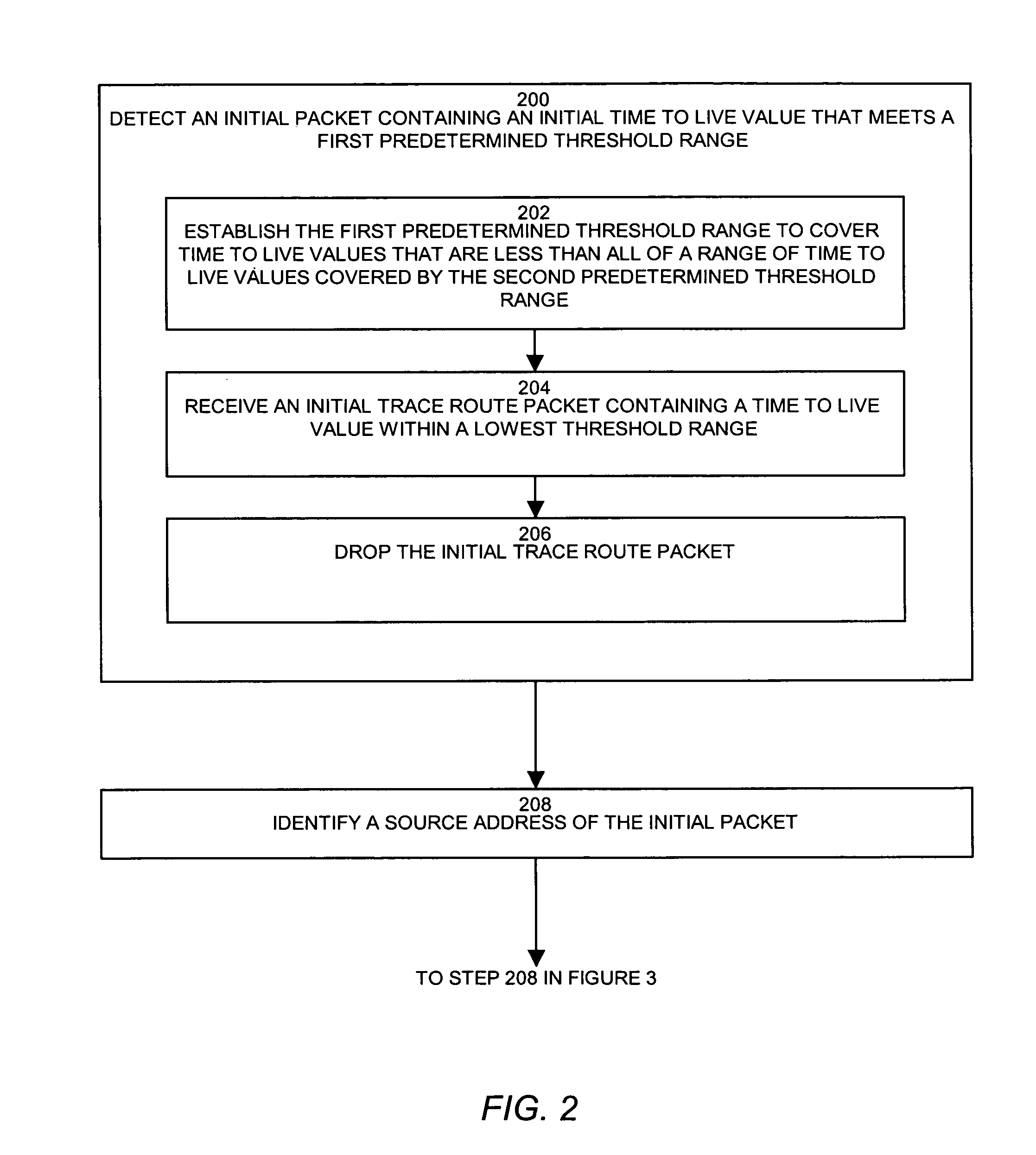
[0020]In an example operation, trace route detection occurs either when a trace detector detects a packet specifying a time to live that falls below or within a threshold value or range, or when the system detects an ICMP time exceed error message. Typically, end host systems detect low time to live values and network devices detect ICMP time exceed error messages, though embodiments are not limited as such. The system provides a trace detector (i.e. a process or application) that prevents network tracing by detecting an initial packet containing an initial time to live value that meets a first predet...


PUM


Abstract

A trace detector prevents network mapping and tracing by detecting an initial packet containing an initial time to live value that meets a first predetermined threshold range. The trace detector identifies a source address of the initial packet and adjusts a threshold time to live range for detection of at least one subsequent trace route or response packet associated with the source address of the initial packet. In response to detecting the subsequent packet(s), the trace detector processes the subsequent packet(s) associated with the source address of the initial packet according to a security policy to prevent a trace process originating the initial packet from tracing a network using the at least one subsequent packet.

Description

BACKGROUND OF THE INVENTION[0001]Modern computer networks are configured as an interconnection of many computer systems links by a set of interconnected data communications devices or nodes such as routers, switches, and gateways. The links between the computers and data communications devices may be physical network cables or wireless links. Typically, a network administrator configures each of the computers and data communications devices in the network with a respective network address. A computer that needs to transmit data to a remote computer across the network creates a series of packets for the data. Each packet includes header information that contains a source network address (e.g. an Internet Protocol or IP address) of the computer originating the packet, as well as a destination address of the computer or other device that is to receive the packet. Other information may be contained in the header as well.[0002]To send a packet to the remote destination computer, the sour...

Claims


Application Information

Patent Timeline
IPC IPC(8): H04L12/50
CPCH04L12/2602H04L43/00H04L63/14H04L2463/146H04L43/16
Inventor MCCOWAN, DAVID JAMESKRAEMER, JEFFREY A.
Owner CISCO TECH INC
Learn More