Hybrid wet electrostatic collector

a technology of electrostatic collectors and wet collectors, which is applied in the direction of electrode cleaning, colloidal chemistry, chemistry apparatuses and processes, etc., can solve the problems of reducing the coulomb force for attracting the charged fine particulate, reducing the collection efficiency, and serious air pollution resulting from automobile exhaust gases

Inactive Publication Date: 2009-10-06
KRIGMONT HENRY
View PDF87 Cites 26 Cited by
  • Summary
  • Abstract
  • Description
  • Claims
  • Application Information

AI Technical Summary

Benefits of technology

[0019]The present invention relates to a hybrid wet electrostatic precipitator for collecting sub-micron and nano-particulate material. The collector can be made up of three concentric tubes or pipes with an internally formed gas path communicating between an inlet and an outlet. A first collector and discharging zone can be provided in the gas path to create a corona discharge to charge particles and to collect particulate. A second collector can be formed by a porous wall which can act as a filtration device. A third collector can be formed by two or more of the concentric circular tubes, one porous and one solid, with a zone of un

Problems solved by technology

In addition, in municipal zones, air pollution resulting from automobile exhaust gases is a serious issue causing even ordinary homes to sometimes have and use an air cleaning apparatus.
This can include polluted air and smoke generated during cooking and the like.
When a large amount of the fine particulate has collected onto the collector electrodes and not removed, the Coulomb force for attracting the charged fine particulate may be reduced thereby reducing the collection efficiency.
In addition, if the we

Method used


Image

  • Hybrid wet electrostatic collector
  • Hybrid wet electrostatic collector
  • Hybrid wet electrostatic collector

Examples


Embodiment Construction

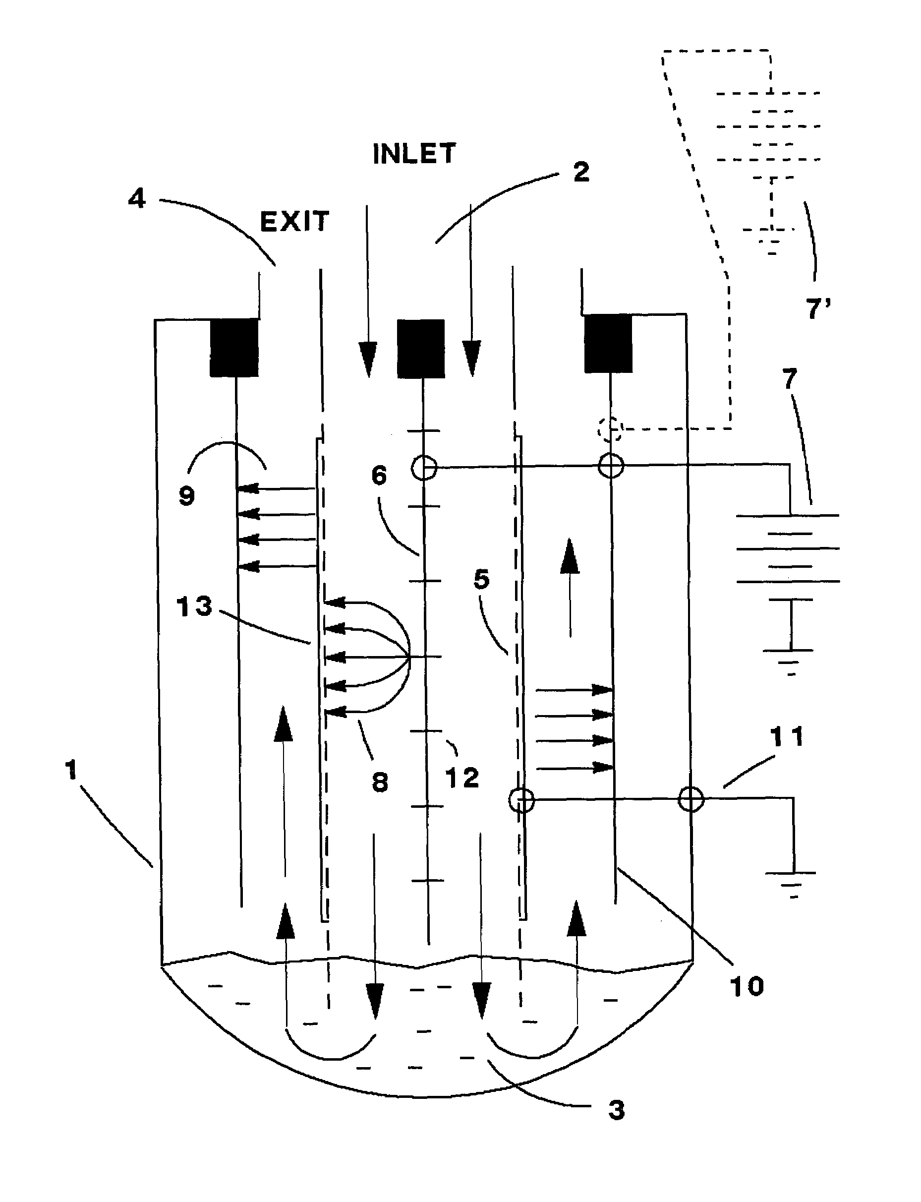
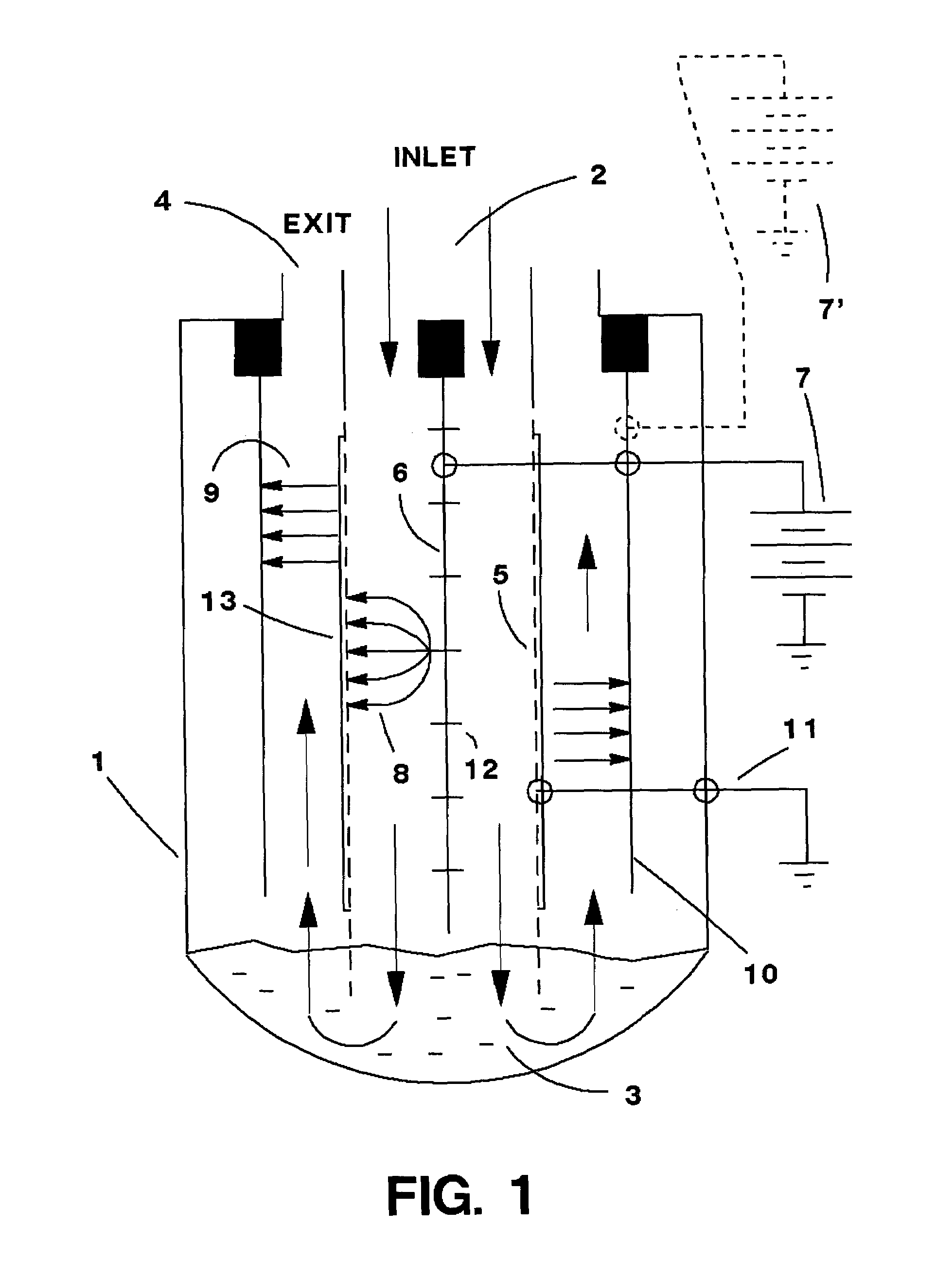
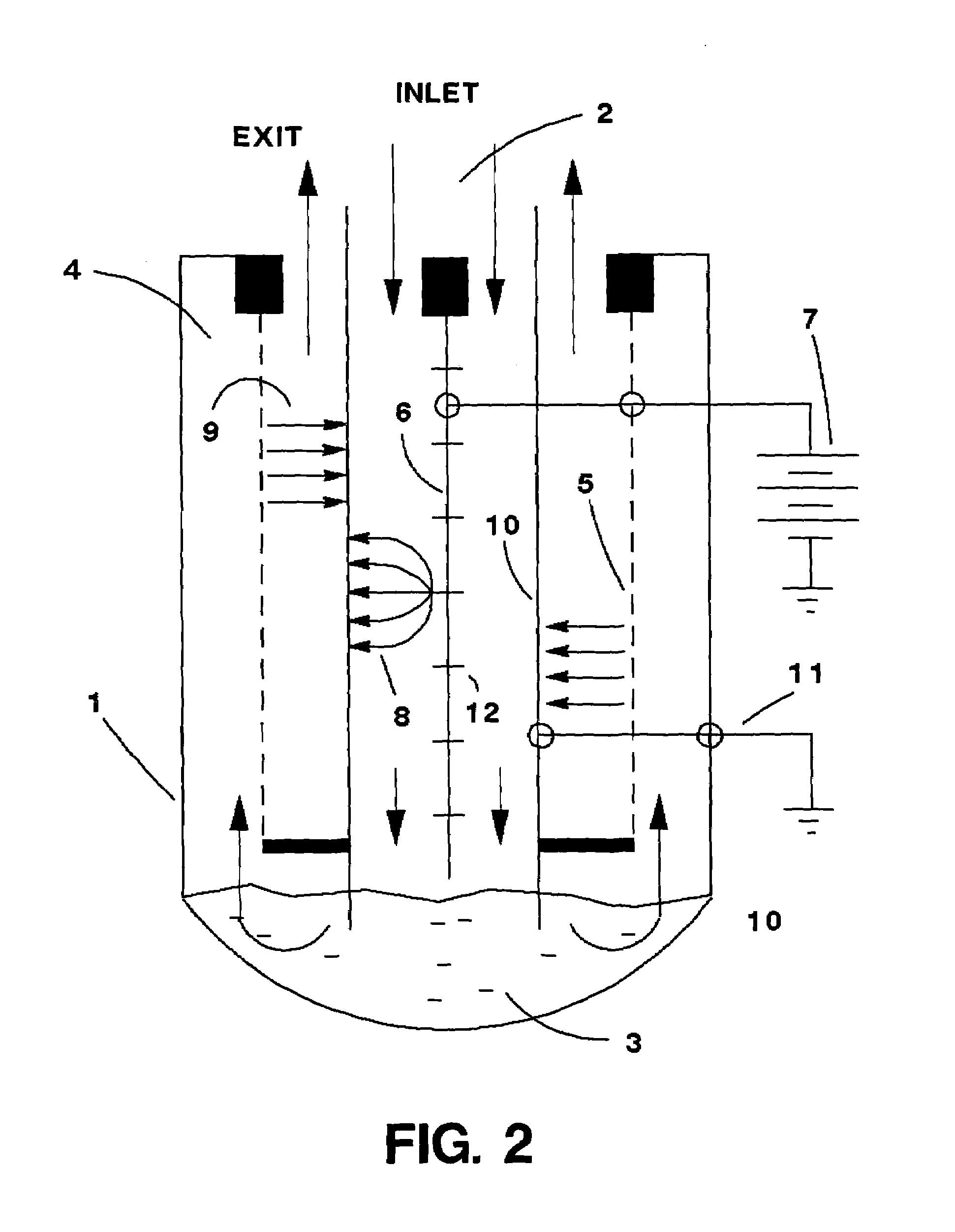
[0025]The present invention relates to a hybrid wet collector for capturing sub-micron and nano-particulate material from an exhaust gas flow. Turning to FIG. 1, an embodiment of the present invention can be seen. An outer metal pipe 1 forms a housing that can contain a concentric inner pipe-shaped porous surface 5. A center rod 6 can have corona discharge electrodes or fingers 12 along its length to create a corona discharge between these electrodes 12 and the porous surface 5. A pool of liquid 3 can fill the bottom of the device up to and above the bottom of the porous tube 5. This forces any of the flow that does not pass through the porous surface 5 to pass through the liquid 3. Between the concentric outer metal housing 1 and the porous surface 5 a second electrode 10 can be located to create a uniform electric field between itself and the porous surface and between itself and the outer housing 1. At least one high-tension electrical potential 7 can be applied between the cente...


PUM


Abstract

A hybrid wet electrostatic precipitator for collecting sub-micron and nano-particulate material. The collector can be made up of three concentric tubes or pipes with an internally formed gas path communicating between an inlet and an outlet. A first collector and discharging zone can be provided in the gas path to create a corona discharge to charge particles and to collect particulate. A second collector can be formed by a porous wall which can act as a filtration device. A third collector can be formed by two or more of the concentric circular tubes, one porous and one solid, with a zone of uniform electric field between them. The porous tube can be either the inner tube or the middle tube. A liquid pool can be placed between the first and third collectors to provide chemical treatment of the gas flow or simply filtration as the gas passes through. A high-tension voltage supply can be used to supply a discharge voltage capable of generating a corona discharge into the flow in the first zone. The corona discharge can cause the fine particulate to become charged and to be captured on the collecting electrode in a zone of uniform field. A second (or the same) high-tension voltage supply can create the uniform electric field.

Description

BACKGROUND[0001]1. Field of the Invention[0002]The present invention relates generally to the field of hybrid collectors and more particularly to a hybrid wet electrostatic collector for collecting sub-micron and nano-particulate material.[0003]2. Description of the Prior Art[0004]There are cases in industrial applications where, before emitting industrial waste gases into the atmosphere such as exhaust gases of boilers in factories or smoke from power generating plants, air purification processing is performed to remove various types of fine particulates contained in these waste gases. These fine particulates include mist and / or dust with powders containing oil, moisture, and / or the like, which can pollute the atmosphere. Direct emission of the industrial waste gases containing the fine particulate into the atmosphere significantly affects the global environment, and hence, it is many times obligatory to perform collection by national or local standards. In addition, in municipal z...

Claims


Application Information

Patent Timeline
IPC IPC(8): B03C3/014
CPCB03C3/014B03C3/08B03C3/16B03C3/09B03C2201/10Y10S55/38
Inventor KRIGMONT, HENRY
Owner KRIGMONT HENRY
Why Eureka
Try Eureka