Flip chip bonding structure
a technology of chip and bonding structure, which is applied in the construction details of electrical apparatuses, manufacturing tools, basic electric elements, etc., can solve the problems of slow electrical resistivity and unsuitable high-speed devices, and achieve the effect of improving the reliability of the semiconductor device and increasing the strength of connection between the connection electrode and the bump
- Summary
- Abstract
- Description
- Claims
- Application Information
AI Technical Summary
Benefits of technology
Problems solved by technology
Method used
Image
Examples
first embodiment
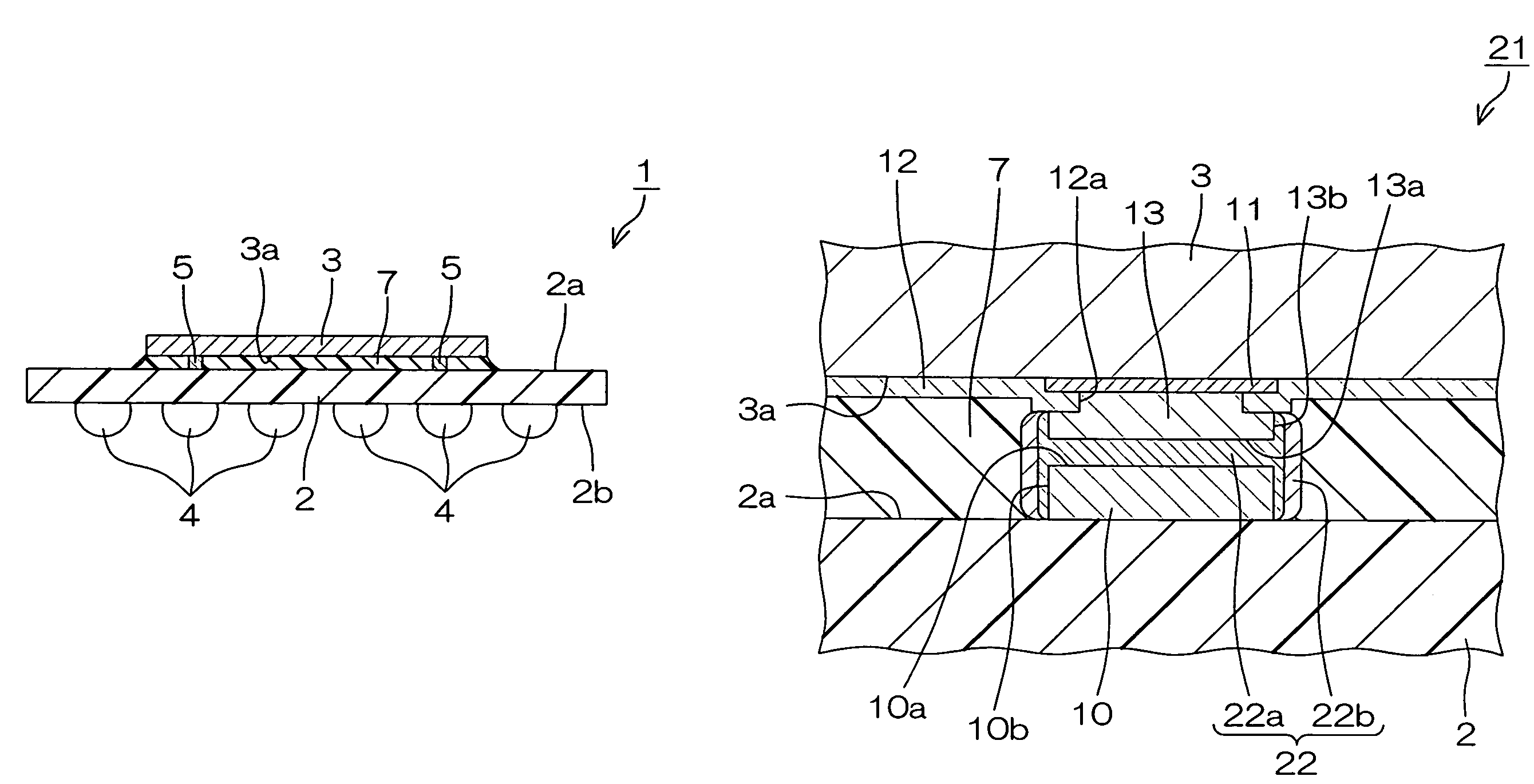
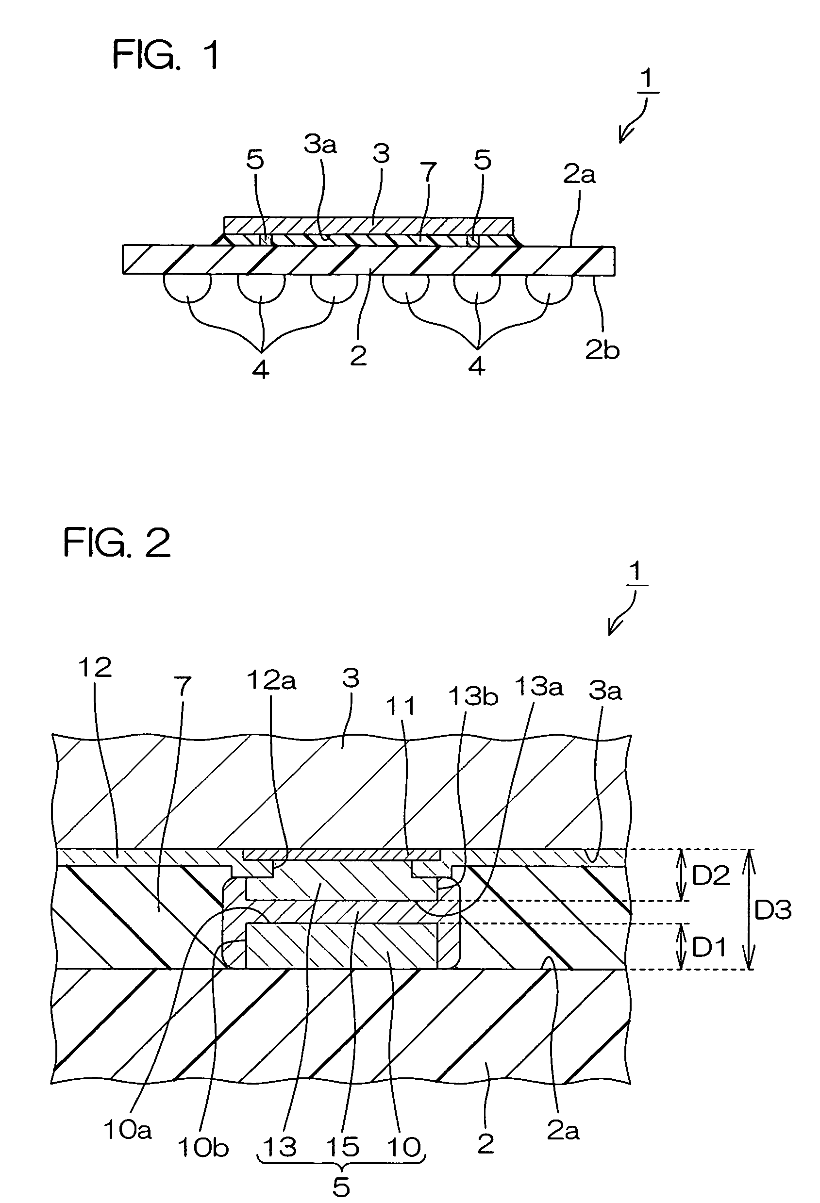
[0041]FIG. 1 is an illustrative sectional view showing a structure of a semiconductor device according to the invention.
[0042]The semiconductor device 1 includes: a wiring board 2 having a connection surface 2a; and a semiconductor chip 3 having a functional surface 3a formed with a functional element and connected to the connection structure 2a as directing its functional surface 3a to the connection surface 2a. The wiring board 2 and the semiconductor chip 3 are mechanically interconnected by means of a conductive member 5 in a manner to maintain a predetermined distance therebetween. The wiring board 2 and the semiconductor chip 3 are also electrically interconnected via the conductive member 5.
[0043]An underfill layer 7 formed from a resin material is interposed in the gap between the wiring board 2 and the semiconductor chip 3. The underfill layer 7 serves not only to protect the functional surface 3a and the conductive member 5 but also to reduce in-plane shear stress along th...
second embodiment
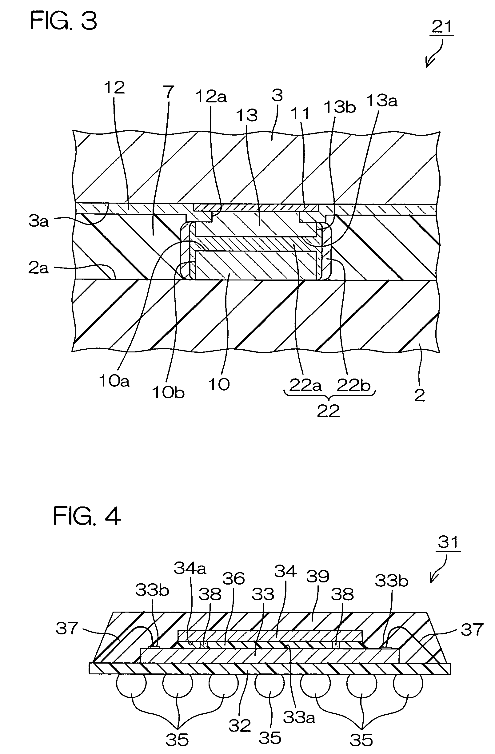
[0059]FIG. 3 is an illustrative sectional view showing a structure of a semiconductor device according to the invention. In FIG. 3, those parts corresponding to the individual parts shown in FIG. 2 are represented by the same reference characters as in FIG. 2, respectively.
[0060]This semiconductor device 21 includes a connecting member 22 in place of the connecting member 15 of the semiconductor device 1 shown in FIG. 2. The connecting member 22 includes: a reacted layer 22a filled in the gap between the connection pad 10 and the bump 13 and formed to cover the side face 10b of the connection pad 10 and the side face 13b of the bump 13; and an un-reacted layer 22b covering lateral sides of the reacted layer 22a.
[0061]The un-reacted layer 22b substantially consists of a low melting point metal (such as tin, lead, indium or an alloy thereof) having a lower solidus temperature than those of the other members of the semiconductor device 21, such as the connection pad 10 and bump 13. On...
third embodiment
[0065]FIG. 4 is an illustrative sectional view showing a structure of a semiconductor device according to the invention.
[0066]This semiconductor device 31 is a so-called multi-chip module and includes: a wiring board 32; a first semiconductor chip 33 overlaid thereon; and a second semiconductor chip 34 stacked on the first semiconductor chip 33. The first and second semiconductor chips 33, 34 respectively possess functional surfaces 33a, 34a each formed with a functional element. The first semiconductor chip 33 is mounted on the wiring board 32 in a so-called face-up state where the functional surface 33a is directed to the opposite side from the wiring board 32.
[0067]The second semiconductor chip 34 is connected to the first semiconductor chip 33 in a so-called face-down state where the functional surface 34a is directed to the functional surface 33a of the first semiconductor chip 33. That is, this semiconductor device 31 has a chip-on-chip structure. The first semiconductor chip ...
PUM
| Property | Measurement | Unit |
|---|---|---|
| electrical resistivity | aaaaa | aaaaa |
| solidus temperature | aaaaa | aaaaa |
| height | aaaaa | aaaaa |
Abstract
Description
Claims
Application Information
 - R&D
- Intellectual Property
- Life Sciences
- Materials
- Tech Scout
- Unparalleled Data Quality
- Higher Quality Content
- 60% Fewer Hallucinations
Browse by: Latest US Patents, China's latest patents, Technical Efficacy Thesaurus, Application Domain, Technology Topic, Popular Technical Reports.
© 2025 PatSnap. All rights reserved.Legal|Privacy policy|Modern Slavery Act Transparency Statement|Sitemap|About US| Contact US: help@patsnap.com


