

Inductor-type synchronous machine
a synchronous machine and synchronous technology, applied in the direction of superconducting magnets/coils, magnetic circuit shapes/forms/construction, magnetic bodies, etc., can solve the problems of power supply destabilization, reduced life, complex structure, etc., to improve the stability of power supply, simplify the structure, and prolong the li
- Summary
- Abstract
- Description
- Claims
- Application Information
AI Technical Summary
Benefits of technology
Problems solved by technology
Method used
Image

Examples
first embodiment
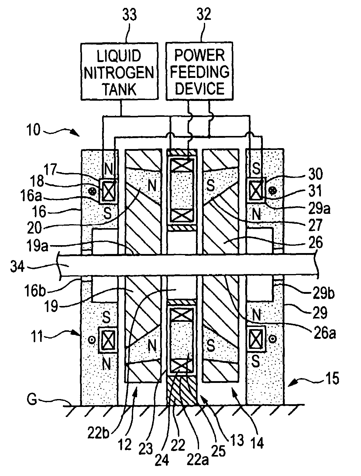
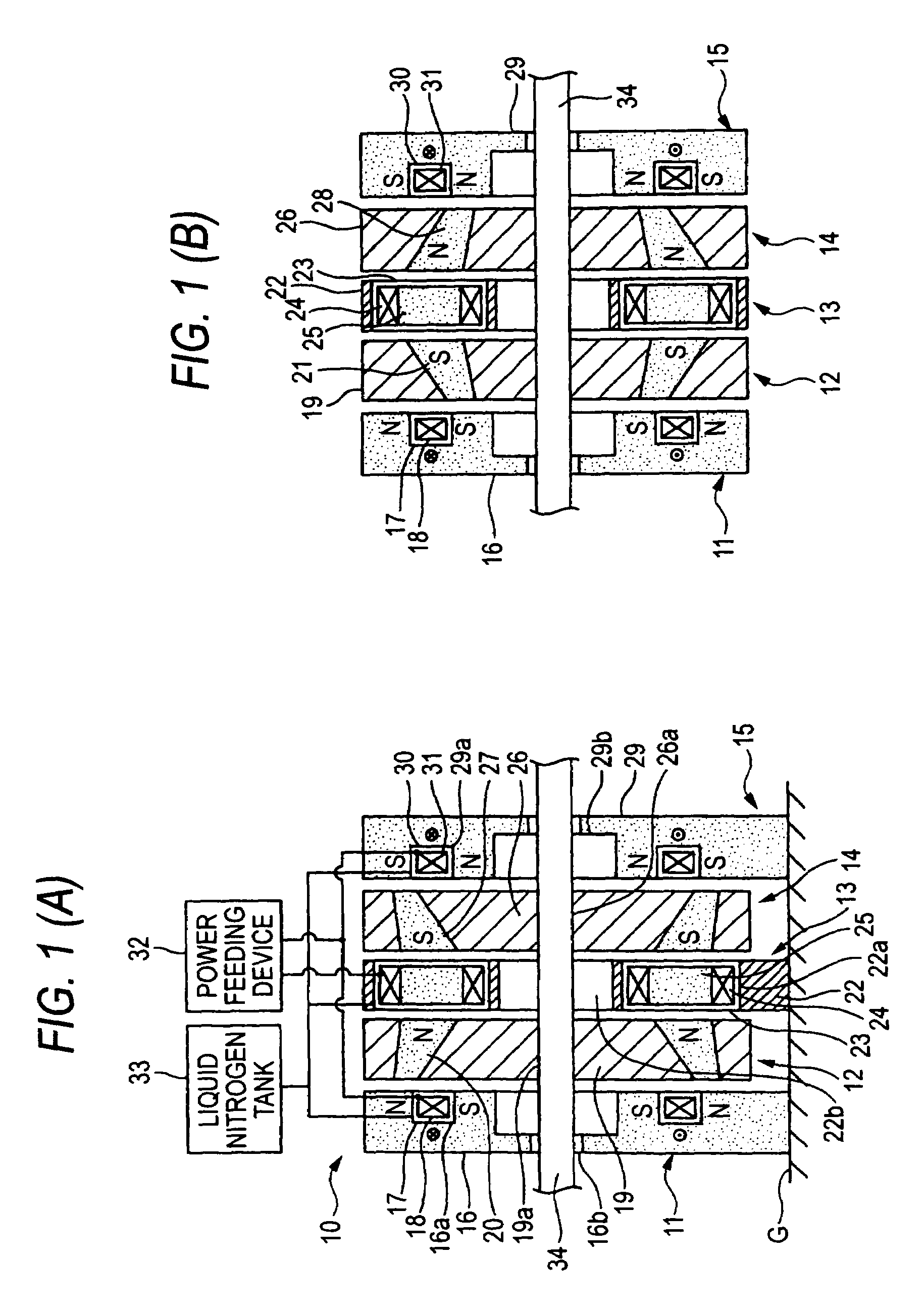
[0069]FIG. 1 shows an inductor-type synchronous motor (a inductor-type synchronous machine) 10 according to a
[0070]The inductor-type synchronous motor 10 has an axial gap structure in which a rotating shaft 34 penetrates a field stator 11, a rotor 12, an armature stator 13, a rotor 14, and a field stator 15 in this order. The field stators 11, 15 and the armature stator 13 are fixed to an installation surface G with a gap being provided with respect to the rotating shaft 34, and the rotors 12, 14 are fit and fixed to the rotating shaft 34 by providing an air gap from the rotating shaft 34 thereto.
[0071]The field stator 11 and the field stator 15 are bilaterally symmetric with respect to reflection. Therefore, one of the stators 15 is representatively shown in FIGS. 3(A) and 3(B).
[0072]Each of the field stators 11, 15 has a yoke 16, 29 made of a magnetic material and is fixed to the installation surface G, an heat-insulating refrigerant container 17, 30 having a vacuum insulation str...
second embodiment
[0109]FIG. 10 shows a
[0110]The second embodiment differs from the first embodiment in that the number of rotors 41, 44 and armature stators 13 is increased.
[0111]More specifically, the rotor 41, the armature stator 13, the rotor 44, and the armature stator 13 are added between the armature stator 13 and the rotor 14 of the first embodiment.
[0112]Each of the rotors 41, 44 includes a disk-shaped support portion 42, 45 which is made of a non-magnetic material and is formed with a rotating shaft mounting hole 42a, 45a for the rotating shaft 34, and a inductor 43, 46 having four magnetic members respectively embedded at a regular intervals along the circumferential direction around the rotating shaft mounting hole 42a, 45a. Each of the inductors 43, 46 has a section, the shape of which is the same as that of the section of the flux collector 25 of the armature stator 13. The support portions 42, 45 are formed of a non-magnetic material such as FRP and stainless steel. The inductors 43, 4...
third embodiment
[0115]FIG. 11 shows a
[0116]The third embodiment differs from the first embodiment in that the rotors 12, 14, the armature stator 13, and the field stator 51 are increased.
[0117]More specifically, the field stator 51, the rotor 12, the armature stator 13, and the rotor 14 are added to between the rotor 14 and the field stator 15 of the first embodiment.
[0118]The field stator 51 includes a yoke 52 which is formed of a magnetic material and is fixed to the installation surface G, an heat-insulating refrigerant container 5.4 having a vacuum insulation structure embedded in the yoke 52, and a field coil 53 which is a winding made of a superconducting member and is accommodated in the heat-insulating refrigerant container 54.
[0119]The yoke 52 has a loose-fitting hole 52b which is drilled at a center thereof such that an outer diameter thereof is larger than the outer diameter of the rotating shaft 34, and a mounting hole 52a drilled in an annular shape around the loose-fitting hole 52b. T...
PUM
| Property | Measurement | Unit |
|---|---|---|
| output power | aaaaa | aaaaa |
| superconducting | aaaaa | aaaaa |
| area | aaaaa | aaaaa |
Abstract
Description
Claims
Application Information