Triaxial membrane accelerometer

a triaxial membrane and accelerometer technology, applied in the direction of acceleration measurement in multiple dimensions, acceleration measurement using interia forces, instruments, etc., can solve the problems of large surface area, cumbersome and expensive solutions, and relatively expensive solutions

Active Publication Date: 2009-10-13
COMMISSARIAT A LENERGIE ATOMIQUE ET AUX ENERGIES ALTERNATIVES
View PDF17 Cites 62 Cited by
  • Summary
  • Abstract
  • Description
  • Claims
  • Application Information

AI Technical Summary

Problems solved by technology

This solution is cumbersome and expensive since it demands three micro-machined components and a mounting of these three components in different but very precise orientations on a common platform.
This type of production involves fabrication by adhesive bonding of several silicon slices (or other materials): in general three slices; the technology is fairly expensive since it is necessary to envisage very deep etchings to define the proof mass, and these deep etchings then require significant surface areas, therefore corresponding bulkiness.
Moreover, these sensors are often produced using substrate transfer techniques, thereby posing problems of dimensional inaccuracy in the direction perpendicular to the substrate, the response of these sensors to accelerations, that is to say the amplitude of the output signal as a function of acceleration, may then be inaccurate, not very linear.
Moreover, the sensitivity axes are not very independent, that is to say an acceleration along one axis induces spurious signals on the outputs corresponding to the other axes.
It is therefore necessary to envisage compensation systems, this also being a drawback.
If it is necessary to slave the position of the mass to a central rest position, as is often desirable to improve performance, it is possible to do so along the horizontal axes, by using interdigitated combs assigned to this slaving, but it is not possible to do so in both directions (up and down) of the vertical axis without considerably complicating the technology.

Method used


Image

  • Triaxial membrane accelerometer
  • Triaxial membrane accelerometer
  • Triaxial membrane accelerometer

Examples


Embodiment Construction

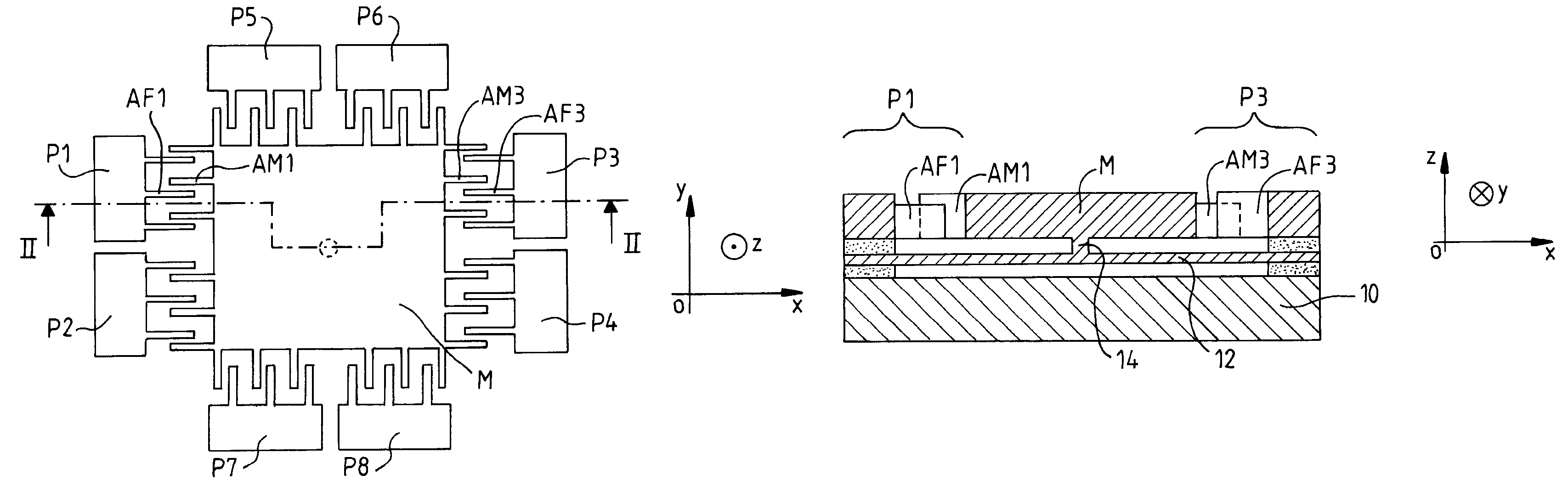
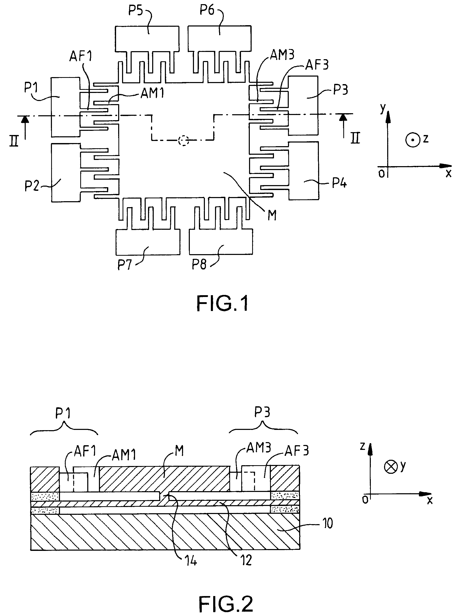
[0028]In the view from above of FIG. 1 is seen a movable proof mass M, of for example rectangular or square or indeed even circular shape, provided on each of its sides with interdigitated capacitive combs. Interdigitated combs are conventionally used for the measurement of the displacements of the proof mass in micro-machined accelerometers. They are variable capacitances having movable plates which are comb fingers secured to the proof mass and fixed plates which are comb fingers secured to fixed portions of a substrate of the accelerometer. There is at least one interdigitated comb on each side, but preferably two combs per side. If the accelerometer is of slaved type there may be additional combs having an electrostatic motor function, but this is not compulsory, the same combs being able to serve for measurement and for slaving.

[0029]The capacitance of each comb at rest is defined by the number of plates in parallel, by the surface area of the individual plates opposite one ano...


PUM


Abstract

The invention relates to accelerometer structures micro-machined according to micro-electronics technologies. The accelerometer according to the invention comprises a substrate, an elastically deformable thin-layer membrane suspended above the substrate and secured to the substrate at its periphery, a proof mass suspended above the membrane and linked to the latter by a central stud, and capacitive interdigitated combs distributed about the mass, having movable plates secured to the mass and fixed plates secured to the substrate. The fixed plates and movable plates of the various combs are of differentiated heights to help in the discrimination of the upward and downward vertical accelerations.

Description

RELATED APPLICATIONS[0001]The present application is based on, and claims priority from, application Ser. No. 06 / 02216, filed Mar. 14, 2006, the disclosure of which is hereby incorporated by reference herein in its entirety.FIELD OF THE INVENTION[0002]The invention relates to micro-machined inertial sensors, that is to say ones made by technologies very close to those which are used in micro-electronics. It relates more particularly to accelerometers.BACKGROUND OF THE INVENTION[0003]Micro-machining makes it possible to produce accelerometers of very reduced size at relatively low cost since it is simultaneously possible to machine a large number of accelerometers on one and the same support slice before dividing them into individual chips.[0004]However, even with this type of technology, it remains desirable to further reduce the dimensions and costs. Specifically, there are more and more applications in the mass-market sector (automobiles, mobile telephony, etc.) and in the profess...

Claims


Application Information

Patent Timeline
Patent Type & Authority Patents(United States)
IPC IPC(8): G01P15/125G01P15/18
CPCB81B3/0062G01P15/18G01P15/0802G01P15/125B81B2201/0235B81B2203/0109B81B2203/0181G01P2015/082G01P2015/084
Inventor ROBERT, PHILIPPEHENTZ, SEBASTIEN
Owner COMMISSARIAT A LENERGIE ATOMIQUE ET AUX ENERGIES ALTERNATIVES
Why Eureka
Try Eureka