
Desalination method

Active Publication Date: 2009-10-13
BP EXPLORATION OPERATING CO LTD +1
View PDF15 Cites 66 Cited by
  • Summary
  • Abstract
  • Description
  • Claims
  • Application Information

AI Technical Summary

Benefits of technology

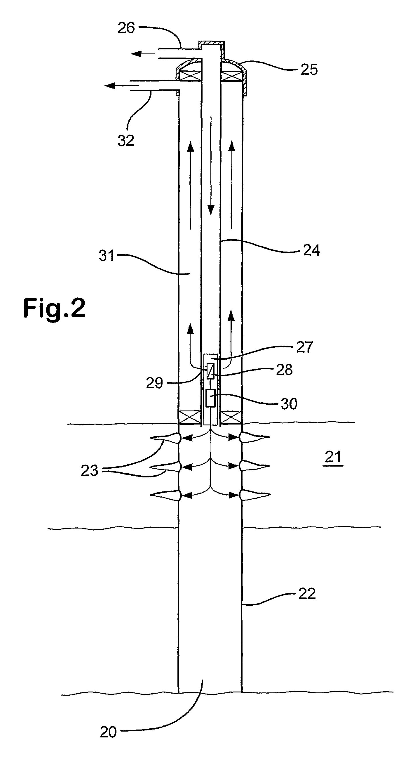
[0020]An advantage of submerging the reverse osmosis desalination assembly in a body of water or of placing the reverse osmosis desalination assembly downhole in a water injection well is that the high salinity water feed to the reverse osmosis unit(s) will be at a higher pressure (owing to the hydrostatic head of the column of high salinity water) than a high salinity water feed to a surface located reverse osmosis desalination plant, for example, a plant located on a platform. Accordingly, the hydrostatic head pressure of the high salinity water feed stream to the reverse osmosis desalination assembly may be used to offset pumping energy requirements and hence power demands of the platform. A disadvantage of surface located reverse osmosis desalination plants is that they have a large footprint and when installed on a platform as a retrofit, often require the addition of platform structure. Thus, a further advantage of submerging the reverse osmosis desalination assembly in a body of water or of locating the assembly downhole in an injection well is that this reduces the space and weight demands of the platform.
[0086]The harmless ions that pass through a selective membrane into the treated injection water may even have a beneficial effect in the formation. For example, potential clay stabilizing ions, such as K+, Na+, Cl−, Br− and OH−, may be passed into the treated injection water product stream and subsequently injected into the formation to beneficially prevent clay swelling or particle migration.

Problems solved by technology

A disadvantage of surface located reverse osmosis desalination plants is that they have a large footprint and when installed on a platform as a retrofit, often require the addition of platform structure.

Method used


Image

  • Desalination method
  • Desalination method
  • Desalination method

Examples


Embodiment Construction

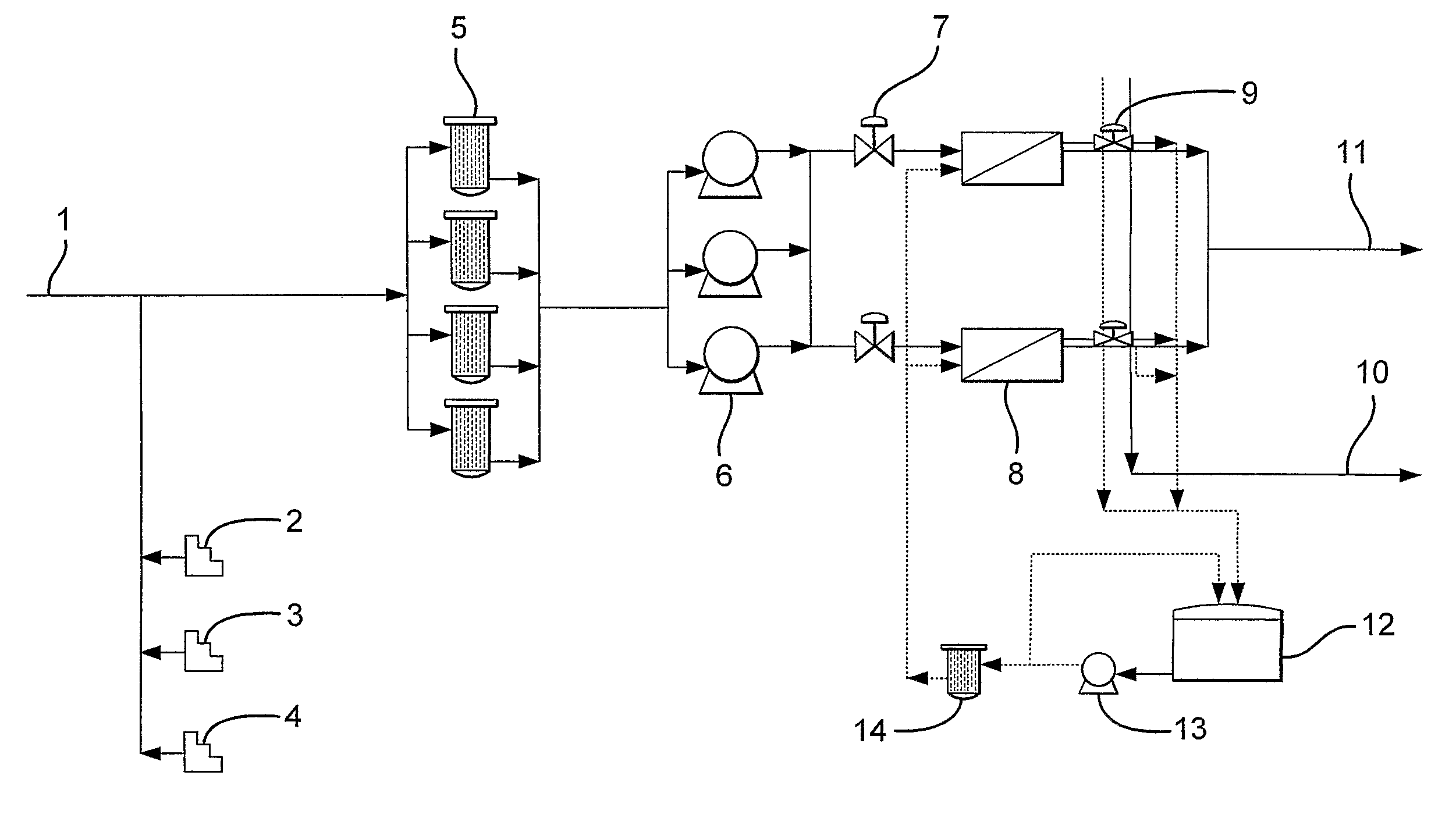
[0090]In the flow diagram of FIG. 1, a high salinity water feed stream 1 is passed through a coarse filter (not shown). A biocide concentrate stream 2, a sodium bisulfite concentrate stream 3 and a scale inhibitor concentrate stream 4 are continuously dosed into the high salinity water feed stream 1 upstream of a plurality of fine filters 5 that are arranged in parallel. The feed stream is then passed via at least one low pressure pump 6 and valves 7 to a plurality of reverse osmosis units 8 that are arranged in parallel. Flow control valves 9 are provided on the outlet for the waste brine stream 10 (retentate). The waste brine stream 10 is discharged to the environment after removing energy therefrom via a Pelton Wheel, a Dual work energy exchanger, or a pressure exchanger (not shown) that is coupled to the rotors of the low pressure pump(s) 6. The low salinity water product stream 11 (retentate) is passed to a storage tank (not shown) before being returned to the surface, for exam...


PUM


Abstract

A method of recovering hydrocarbons from a porous subterranean hydrocarbon-bearing formation comprising the steps of: a) feeding to at least on reverse osmosis unit of a desalination assembly a high salinity water feed stream having a total dissolved solids content (total salinity) of at least 10,000 ppm; b) driving a portion of the high salinity water feed stream across a membrane in the reverse osmosis unit of the desalination assembly at a pressure above the osmotic pressure of the high salinity water feed stream while excluding at least a portion of the dissolved solids from crossing said membrane to produce a treated low salinity water product stream having a total salinity of less than 5,000 ppm and a concentrated waste brine stream wherein the hydrostatic head exerted by the high salinity water feed stream on the feed side of the membrane provides at least a major component of the pressure required to overcome the osmotic pressure; c) injecting the low salinity water product stream into the hydrocarbon-bearing formation from an injection well; d) displacing the hydrocarbons with the low salinity water product stream toward an associated production well; and e) recovering hydrocarbons from the formation via the production well.

Description

[0001]This application is the U.S. National Phase of International Application PCT / GB2005 / 001939, filed 19 May 2005, which designated the U.S. PCT / GB2005 / 001939 claims the benefit of provisional Application No. 60 / 575,100 filed 28 May 2004. The entire content of these applications are incorporated herein by reference.[0002]The present invention relates to a method of recovering hydrocarbons from a porous subterranean hydrocarbon-bearing formation by injecting a low salinity water into the formation wherein the low salinity water is produced using an underwater or downhole reverse osmosis desalination assembly that relies on hydrostatic head pressure to provide at least a major component of the pressure required to overcome the osmotic pressure.BACKGROUND OF THE INVENTION[0003]It has long been known that only a portion of the oil can be recovered from a permeable oil-bearing subterranean formation as a result of the natural pressure of the reservoir. So-called secondary recovery tech...

Claims


Application Information

Patent Timeline
IPC IPC(8): E21B43/20E21B43/38B01D61/10E21B43/36
CPCB01D61/025B01D61/04E21B43/385E21B43/36E21B43/20Y02A20/131B01D61/10E21B43/00E21B43/38B01D61/00B01D61/02
Inventor CHRISTOPHER, CHARLES ARLESCOLLINS, IAN RALPHFRAMPTON, HARRYVISSER, FOLKERT PAUL
Owner BP EXPLORATION OPERATING CO LTD
Learn More