
Optical coherence imaging systems having a reduced effective linewidth and methods of using the same

a coherence imaging and optical transmission path technology, applied in the field of optical coherence imaging systems, can solve the problems and achieve the effect of reducing the effective linewidth of the imaging system

Inactive Publication Date: 2009-10-13
BIOPTIGEN
View PDF6 Cites 66 Cited by
  • Summary
  • Abstract
  • Description
  • Claims
  • Application Information

AI Technical Summary

Benefits of technology

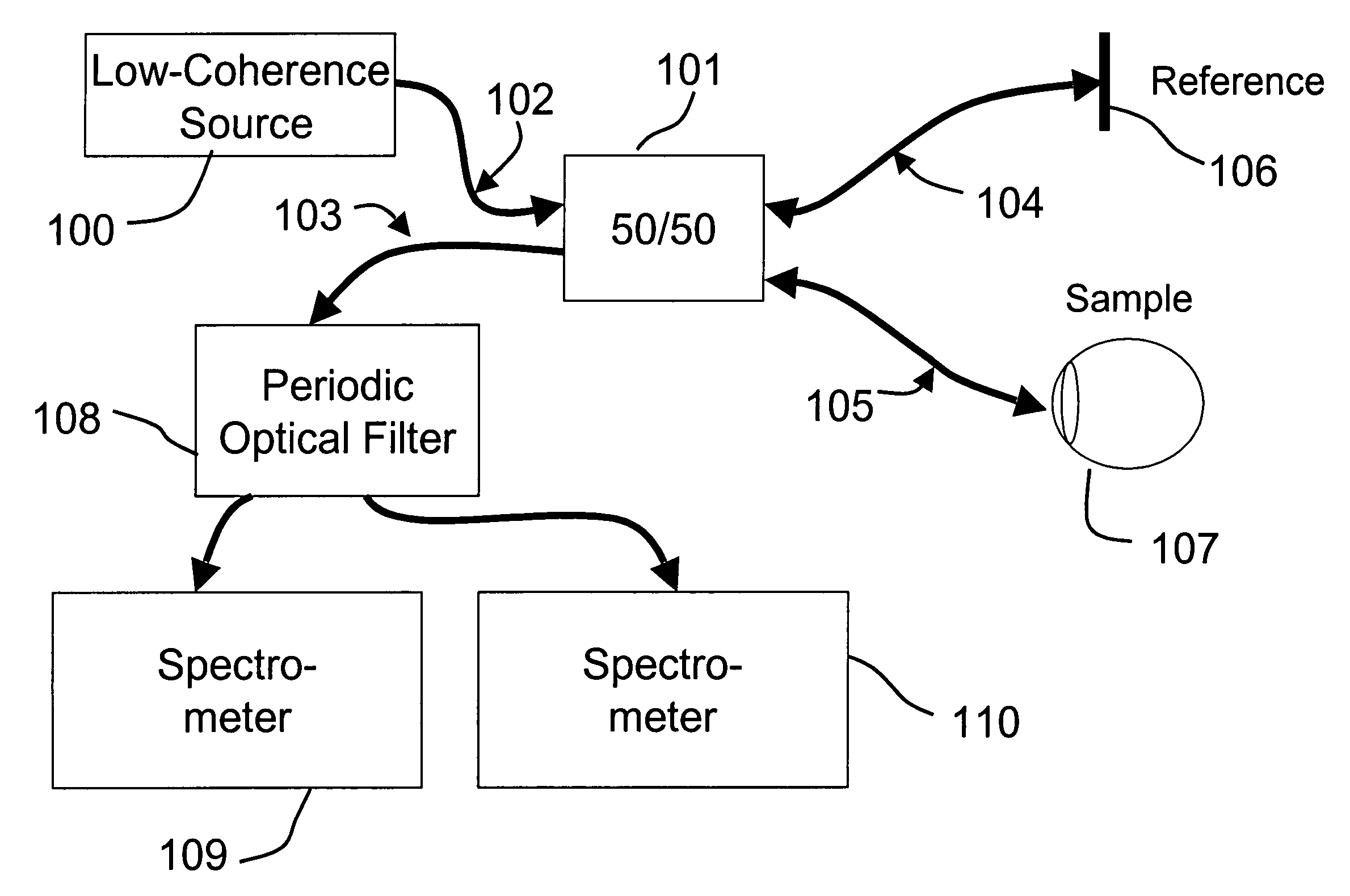
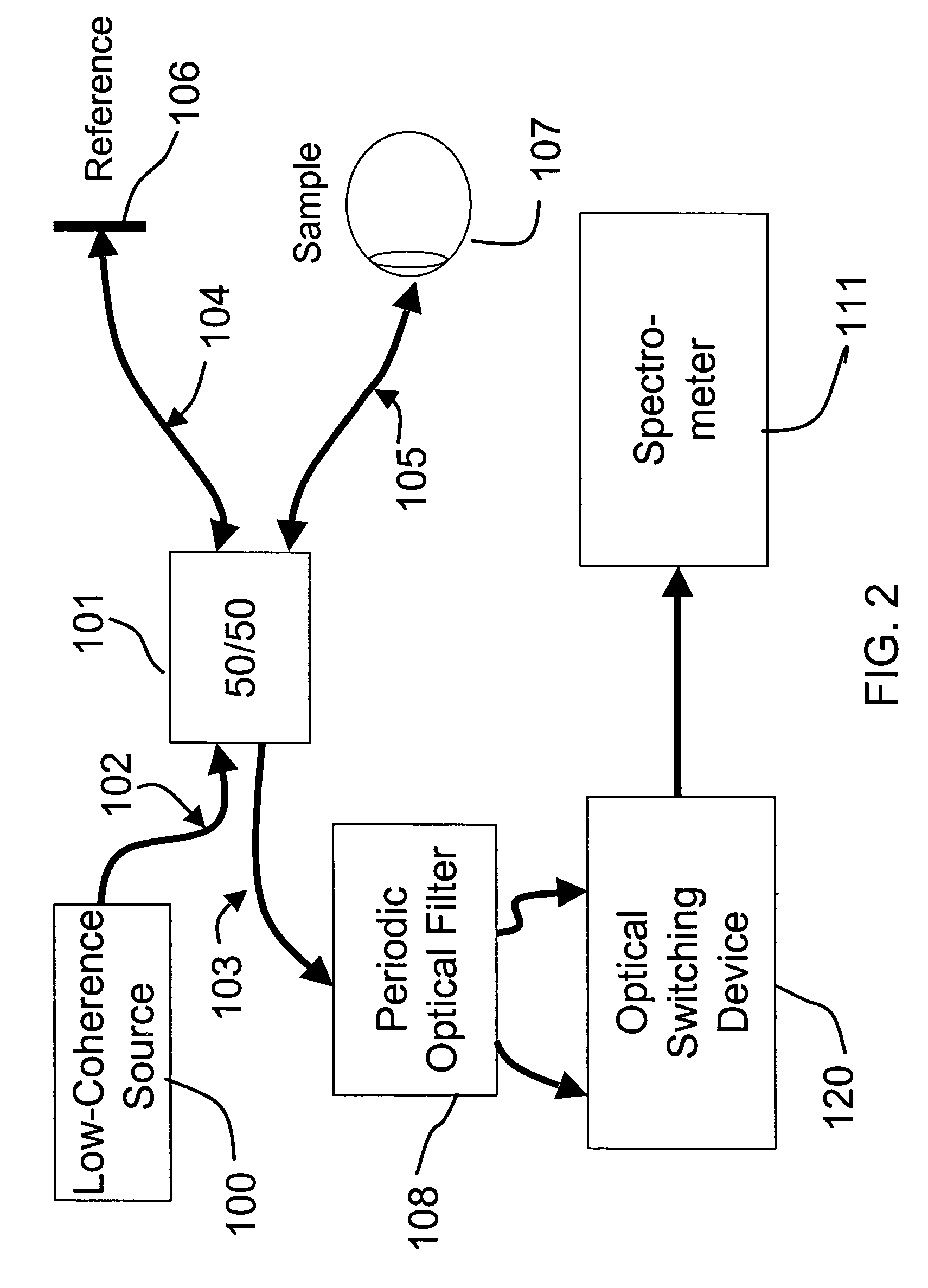
"The present invention relates to frequency domain optical coherence imaging systems that have a reduced effective linewidth, which can be achieved by using an optical source with a broadband or low coherence source and a periodic optical filter. The optical source can be a tunable optical source and the periodic optical filter can include an optical splitter and a detector arm. The system can also include multiple optical detectors and a spatial mask to selectively couple the optical detectors to the detector arm. The periodic optical filter can be a tunable filter with a selectable output wavelength comb spectra, tuning rate, resolution, and / or finesse. The system can also include multiple periodic optical filters with different arms of the system. The optical source can include a plurality of tunable optical sources and the optical detectors can be spectrometers. The technical effects of the invention include improved image quality, reduced linewidth, and improved depth of field."

Problems solved by technology

The optical transmission path between the optical source and the optical detector reduces an effective linewidth of the imaging system.

Method used


Image

  • Optical coherence imaging systems having a reduced effective linewidth and methods of using the same
  • Optical coherence imaging systems having a reduced effective linewidth and methods of using the same
  • Optical coherence imaging systems having a reduced effective linewidth and methods of using the same

Examples


Embodiment Construction

[0035]Specific exemplary embodiments of the invention now will be described with reference to the accompanying drawings. This invention may, however, be embodied in many different forms and should not be construed as limited to the embodiments set forth herein; rather, these embodiments are provided so that this disclosure will be thorough and complete, and will fully convey the scope of the invention to those skilled in the art. The terminology used in the detailed description of the particular exemplary embodiments illustrated in the accompanying drawings is not intended to be limiting of the invention. In the drawings, like numbers refer to like elements.

[0036]As used herein, the singular forms “a”, “an” and “the” are intended to include the plural forms as well, unless expressly stated otherwise. It will be further understood that the terms “includes,”“comprises,”“including” and / or “comprising,” when used in this specification, specify the presence of stated features, integers, ...


PUM


Abstract

Frequency domain optical coherence imaging systems have an optical source, an optical detector and an optical transmission path between the optical source and the optical detector. The optical transmission path between the optical source and the optical detector reduces an effective linewidth of the imaging system. The optical source may be a broadband source and the optical transmission path may include a periodic optical filter.

Description

RELATED APPLICATIONS[0001]The present application claims priority from U.S. Provisional Application No. 60 / 703,376, filed Jul. 28, 2005, the disclosure of which is hereby incorporated herein in its entirety by reference.BACKGROUND OF THE INVENTION[0002]The present invention relates to imaging systems and, more particularly, to optical-coherence imaging systems.[0003]A variety of approaches to imaging using optical coherence tomography (OCT) are known. Such systems may be characterized as Fourier domain OCT (FD-OCT) and time domain OCT (TD-OCT). FD-OCT generally includes swept source (SS) and spectral domain (SD), where SD systems generally use a broadband source in conjunction with a spectrometer rather than a swept laser source and a photodiode(s). TD systems generally rely on movement of a mirror or reference source over time to control imaging depth by providing coherence depth gating for the photons returning from the sample being imaged. Both systems use broadband optical sourc...

Claims


Application Information

Patent Timeline
Patent Type & Authority Patents(United States)
IPC IPC(8): G01B9/02
CPCA61B3/102G01N21/4795G01B9/02007G01B9/02044G01B9/02008G01B9/02091G01B9/02004A61B3/1225A61B5/0066G01B2290/45
Inventor IZATT, JOSEPH A.BUCKLAND, ERIC L.BROWN, WILLIAM J.
Owner BIOPTIGEN
Learn More