Servo motor control system

a technology of servo motors and control systems, applied in the direction of electric programme control, ignition automatic control, program control, etc., can solve the problems of difficult thermal sealing, inability to make desired parts to be end-sealed sandwiched between end sealers, and inability to control the acceleration of electronic cams. to be smooth and easy to opera

Active Publication Date: 2009-10-13
ORMON CORP
View PDF10 Cites 9 Cited by
  • Summary
  • Abstract
  • Description
  • Claims
  • Application Information

AI Technical Summary

Benefits of technology

[0016]It is therefore an object of this invention to provide a servo motor control system such that the acceleration of an electronic cam can change smoothly between a non-synchronized control section and a synchronized control section.
[0017]A method related to this invention is for the control of an electronic cam using a servo motor, being provided with a synchronized control section where control is carried out for moving a follower shaft serving as a controlled object in synchronism with a main shaft position and a non-synchronized control section where control is carried out for moving the follower shaft from the ending position of the synchronized control section to the starting position of the next synchronized control section. A fifth-order function for position control of the electronic cam, a fourth-order function for speed control of the electronic cam and a third-order function for acceleration control of the electronic cam are used in the non-synchronized control section such that operation of the electronic cam at transition points between the synchronized control section and the non-synchronized control section is smoothly controlled.

Problems solved by technology

This sealing method is convenient in the case of a film material which cannot be melted and softened easily and with which a thermal sealing is difficult because the heating time can be made relatively long.
In many situations, however, the desired part to be end-sealed cannot be made to be sandwiched between the end sealers if the speed of motion of the sealing surfaces of the end sealers is controlled to be constant throughout the period during which the end sealers make a complete revolution.
By this technology, however, the acceleration of the electronic cam could not be controlled to be smooth near the boundary point between a non-synchronized control section and the next synchronized control section.
If the acceleration waveform is discontinuous between the two sections, there is a probability of generation of vibrations.
In particular, as a number of products to be produced per unit time is increased and a high-speed operation is required, the occurrence of vibrations is likely and becomes a source of obstacles against a high-speed control.
By an off-line method of producing a cam table for the control of an electronic cam, furthermore, it is not possible to produce a non-synchronous cam curve on real-time for specifying a change in the starting position of synchronization, range of synchronization and synchronization ratio of the synchronization curve or the passing of a specified position in order to prevent a machine interference.
This makes it necessary to produce a cam table, adversely affecting the efficiency.

Method used


Image

  • Servo motor control system
  • Servo motor control system
  • Servo motor control system

Examples


Embodiment Construction

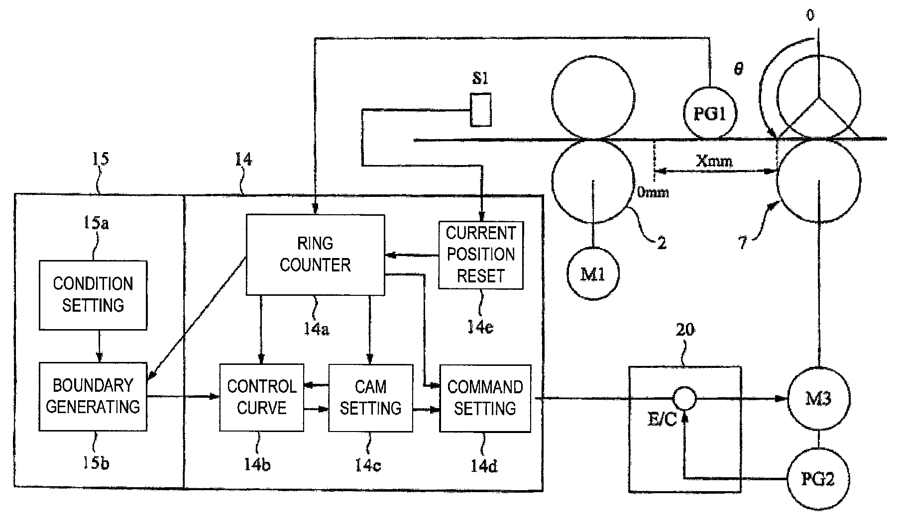
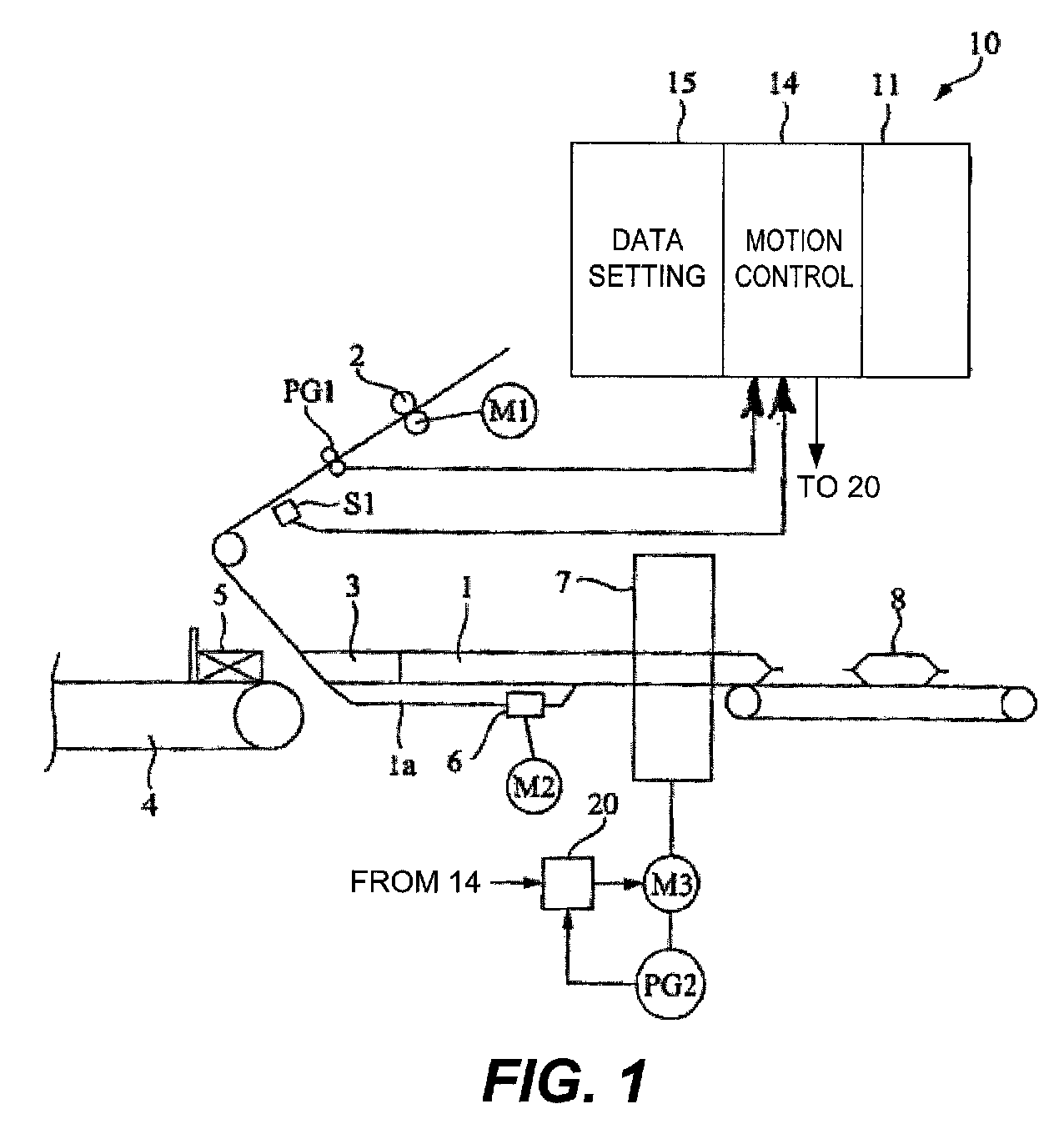
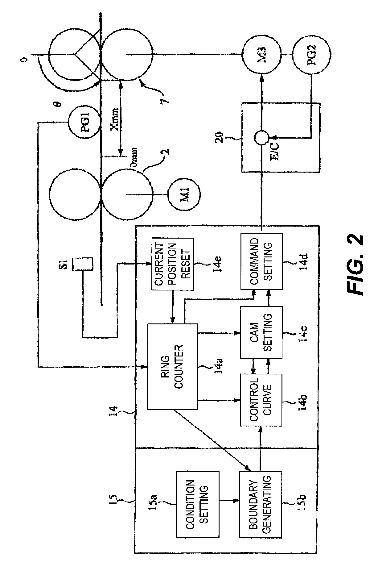
[0057]FIG. 1 shows a control system of a packaging machine as an example of control system embodying this invention. To explain the packaging machine serving as the object of control, numeral 1 indicates a packaging film which is sandwiched between a pair of feed rollers 2 and pulled out continuously at a constant speed by the rotary motion of these feed rollers 2. The packaging film 1 is then formed into the shape of a bag by passing over a bag former 3. An article transporting device 4 such as a finger conveyer is disposed on the upstream side of the bag former 3, serving to transport articles 5 to be packaged at fixed intervals and to supply them into the bag former 3 at a specified timing. As a result, the packaging film 1 formed in a cylindrical shape comes to enclose the articles 5 at the fixed intervals and is transported in this condition.

[0058]A center sealing apparatus 6 and an end sealing apparatus 7 are provided on the downstream side of the bag former 3. The center seal...


PUM


Abstract

An electronic cam using a servo motor is controlled such that its motion including its acceleration will be connected between synchronized and non-synchronized control sections. A controlled object is moved at a fixed speed during the synchronized control section. A fifth-order function for position control of the electronic cam, a fourth-order function for speed control of the electronic cam and a third-order function for acceleration control of the electronic cam are used in the non-synchronized control section such that operation of the electronic cam at transition points between the synchronized control section and the non-synchronized control section is smoothly controlled.

Description

[0001]Priority is claimed on Japanese Patent Application 2004-332566 filed Nov. 17, 2004.BACKGROUND OF THE INVENTION[0002]This invention relates to a servo motor control system.[0003]Industrial machines of many kinds such as a packaging machine make use of a motor such as a servo motor with which speed can be controlled as the source of driving power. A packaging machine comprises a main body part, a film supplying means for pulling out an elongated packaging film to continuously supply it to the main body part and an article supplying means for supplying articles to be packaged to the main body part intermittently at specified intervals. The main body part is adapted to carry out a suitable fabrication process on the supplied film so as to be able to enclose the articles to be packaged (say, into the form of a bag or a pocket) and also to cause the articles to be enclosed in the film. The enclosed articles are transported inside the packaging film, and the packaging film is sealed ...

Claims


Application Information

Patent Timeline
Patent Type & Authority Patents(United States)
IPC IPC(8): G05B19/18G05B13/00
CPCG05B7/02G05B19/19Y10T74/2101G05B2219/50231G05B2219/50233G05B2219/34341G05B19/418
Inventor MAEDA, HIROYUKI
Owner ORMON CORP
Why Eureka
Try Eureka