Eureka AIR delivers breakthrough ideas for toughest innovation challenges, trusted by R&D personnel around the world.

Systems and methods for handheld projection displays

Active Publication Date: 2009-10-20
PHOTONEDGE
View PDF8 Cites 3 Cited by
  • Summary
  • Abstract
  • Description
  • Claims
  • Application Information

AI Technical Summary

Benefits of technology

[0009]In a first embodiment, a handheld projection system employing a first lens array and a second lens array for processing a plurality of color light signals where a single LCOS display panel spatially modulates the color light signals which forms an image onto a screen. In a second embodiment, a handheld projection system employing a first LCOS display panel for spatially modulating a S-polarization component onto a screen and a second LCOS display panel for spatially modulating a P-polarization component onto the screen. In a third embodiment, a handheld projection system employs a field lens positioned between a polarization beam splitter and a LCOS display panel that makes illumination telecentric, which simplifies the optics in a condenser as well as reducing the size of the condenser. In a fourth embodiment, a handheld projection system employing a separate set of a first lens array, a second lens array, and a condenser associated with each color light signal, producing an end product that is more compact in design. In a fifth embodiment, a handheld projection system employing a transmissive LCD display panel with the additions of a second polarizer and a folding mirror.

Problems solved by technology

Currently, the size of a display on these devices is limited by the dimension of the device itself.

Method used


Image

  • Systems and methods for handheld projection displays
  • Systems and methods for handheld projection displays
  • Systems and methods for handheld projection displays

Examples


first embodiment

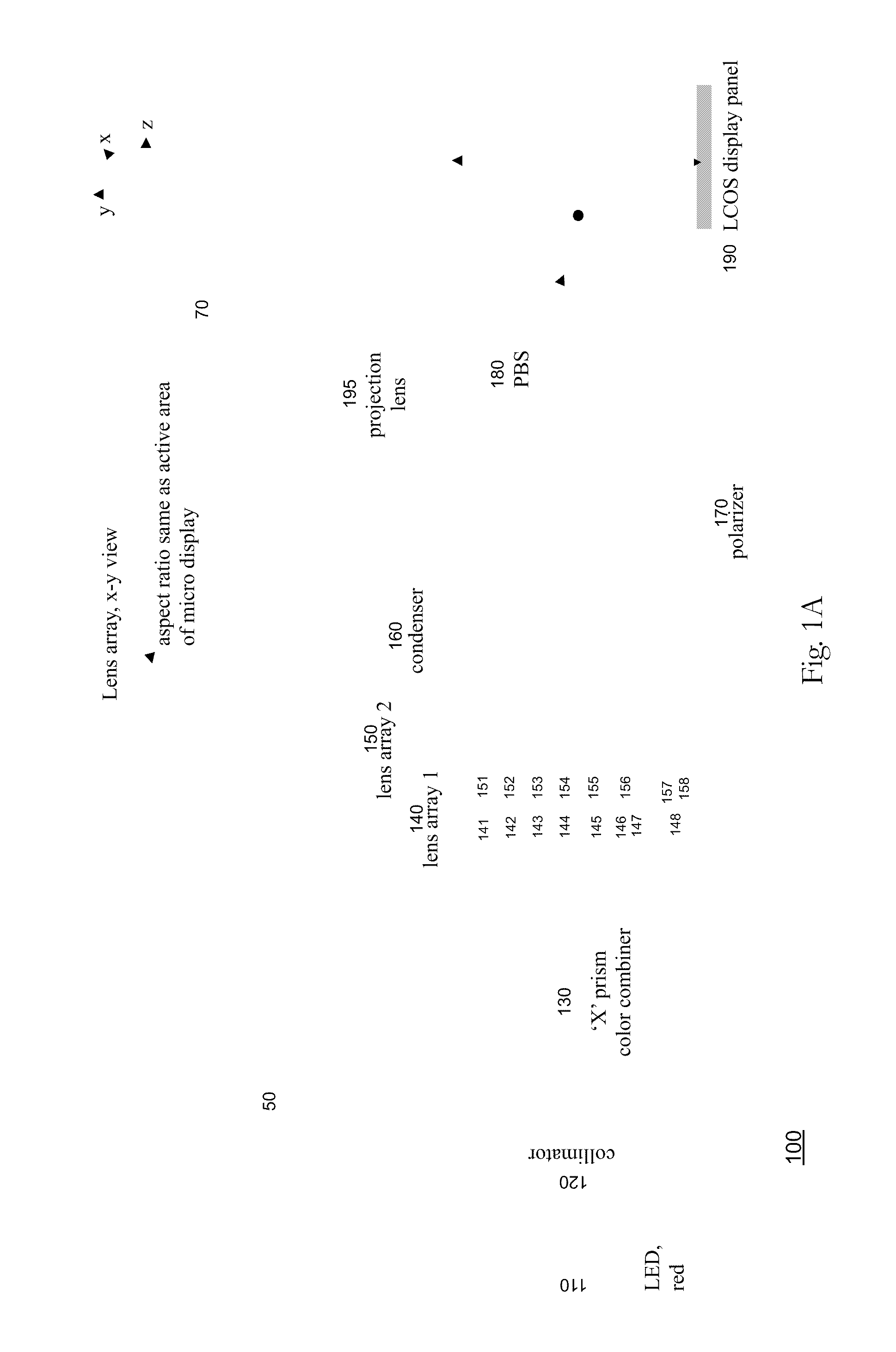
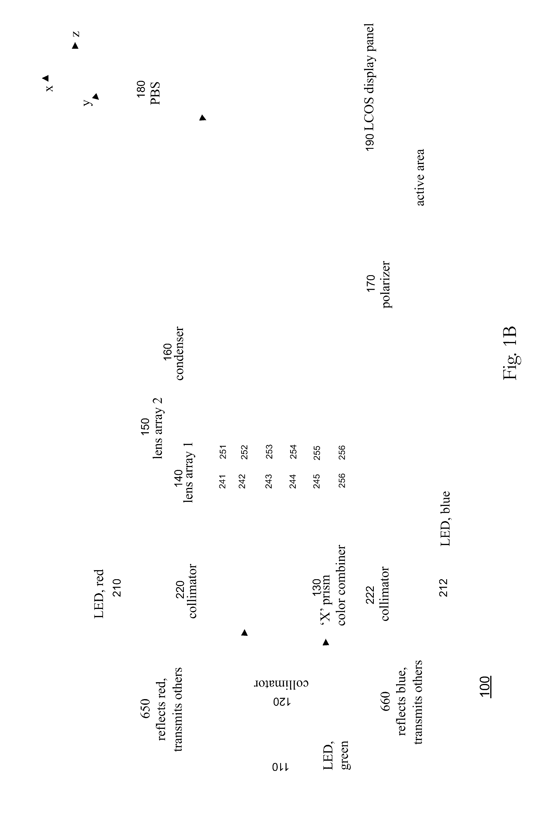
[0026]Referring now FIG. 1A, there is shown a structural diagram of Y-Z view in a handheld projection system 100 employing a LCOS display panel 190. The term “LCOS display panel” is used interchangeably with “LCOS microdisplay”, or referring to a LCOS chip. The handheld projection system 100 generally can be viewed as comprising two main sections: illumination optics 50 and projection optics 70. A light emitting diode (LED) 110 projects a light signal that is collimated by a collimator 120 into a relatively narrow diverging cone toward an X-prism color combiner 130 (also referring to as a prism plate color combiner). The light emitting diode 110 is of red color. The X-prism color combiner 130 transmits the red color light to a first lens array 140.

[0027]The first lens array 140 includes a plurality of lenslets in a two-dimensional array. Lenslet 141, 142, 143, 144, 145, 146, 147 and 148 are examples. A second lens array 150 includes a plurality of lenslets in a two-dimensional array...

second embodiment

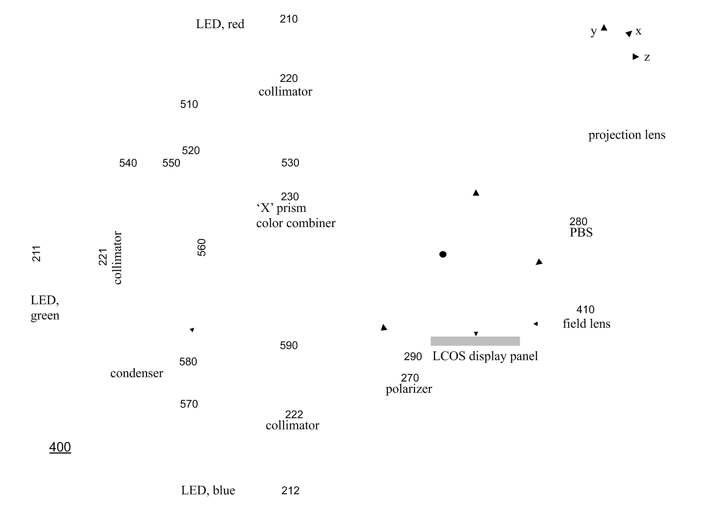
[0052]In FIG. 2, there is shown a structural diagram illustrating a handheld projection system 200 employing a pair of LCOS display panels for recapturing the lost polarization. FIG. 2 is a Y-Z view in which the red and blue LEDs are not shown. As can be observed in FIGS. 1A and 1B, half of the light from the light source is lost if the light source is non-polarized. The handheld projection system 300 adds a second LCOS display panel 310 to recapture the lost polarization, thereby increasing the brightness of an image. In an alternative embodiment, a polarization converter can be used instead of the second LCOS display panel 310, when Etendue of the light source is less than the Etendue of the display panel. Etendue is typically the product of the source (or display) area and the solid angle of emitting cone (or acceptance cone of the display panel). A polarization conversion system as illustrated in FIG. 7A can be inserted between the condenser and the PBS to increase illumination ...

third embodiment

[0053]As shown in FIG. 3, there is a structural diagram illustrating a handheld projection system 300 employing a LCOS display panel with a field lens 410. The field lens 410 is placed between the polarization beam splitter 180 and the LCOS display panel 190, in close proximity to the display panel 190. The advantage of using the field lens 410 as shown is that it simplifies the optics in the condenser 160 as well as reducing the size of the condenser 160. In a first order approximation, the focal length of the field lens 410 should be equal to the focal length of the condenser 160.


PUM


Abstract

Systems and methods are described employing a first lens array and a second lens array that are separated by one focal length that receives a plurality of colors signals from an X-prism and transmits to a condenser for overlapping lenslet images onto a display panel, such as a LCOS or LCD display panel. The first lens array includes a plurality of lenslets where each lenslet in the first lens array corresponds with each lenslet in a plurality of lenslets in the second lens array. The lenslets can be either refractive, defractive, or a combination of refractive and defractive.

Description

RELATED APPLICATION DATA[0001]This application claims the benefit of U.S. Provisional Patent Application No. 60 / 635,050 entitled Head-Mount Display and Handheld Projection Displays, filed on 13 Dec. 2004, which is incorporated herein by reference.BACKGROUND OF THE INVENTION[0002]1. Field of the Invention[0003]The present invention relates generally to displays and more particularly to handheld projection displays with a larger visual screen.[0004]2. Description of Related Art[0005]In the new world that is frequently characterized, metaphorically speaking, that the world is flat, a mobile computing device will be at the central platform in which an individual is tied to the computing universe, replacing a personal desktop computer, as information technology, electronic mails, the Internet, instant messaging, and global positioning systems, become increasingly 24 / 7 in one's daily live in working in a fluid society and an ever-integrated global economy. Current music players possess or...

Claims


Application Information

Patent Timeline
IPC IPC(8): G03B29/00G02B7/28G02F1/1335G02F1/135H04N5/74G03B21/14G03B21/20G03B21/28
CPCG02B3/0062H04N9/3197G03B21/14H04N9/3152H04N9/3167H04N9/3173G02F1/133603G02F1/13362G02F1/136277G02F2001/13355G02F2001/133607G02F1/13355G02F1/133607
Inventor PENG, SONG
Owner PHOTONEDGE
Why Eureka
Eureka Blog
Learn More