Equipment front end module

a technology for front end modules and equipment, applied in the field of substrate processing, can solve the problems of affecting the reliability of equipment front end modules, and the degree of movement of robots, so as to achieve the effect of simple and less expensive robots, easy programing, and reliable operation

Inactive Publication Date: 2009-10-20
KLA TENCOR TECH CORP
View PDF35 Cites 38 Cited by
  • Summary
  • Abstract
  • Description
  • Claims
  • Application Information

AI Technical Summary

Benefits of technology

[0051]Embodiments of the present invention can utilize much simpler and less expensive robots than prior art EFEM systems. R-theta robots are easier to program, more reliable and have a longer mean time between failures. These features reduce the costs of setting up and operating an EFEM system. In addition, EFEM systems according to embodiments of the present invention can have a smaller footprint, i.e., take up less space on the floor of a fab since they do not rely on a side-by-side arrangement of the load ports.

Problems solved by technology

The extra degree of movement makes the robot complex in terms of both mechanical design and motion control hardware and software.
This complexity can account for as much as 30% of the cost of an equipment front end module.

Method used


Image

  • Equipment front end module
  • Equipment front end module
  • Equipment front end module

Examples


Embodiment Construction

[0029]Although the following detailed description contains many specific details for the purposes of illustration, anyone of ordinary skill in the art will appreciate that many variations and alterations to the following details are within the scope of the invention. Accordingly, the exemplary embodiments of the invention described below are set forth without any loss of generality to, and without imposing limitations upon, the claimed invention.

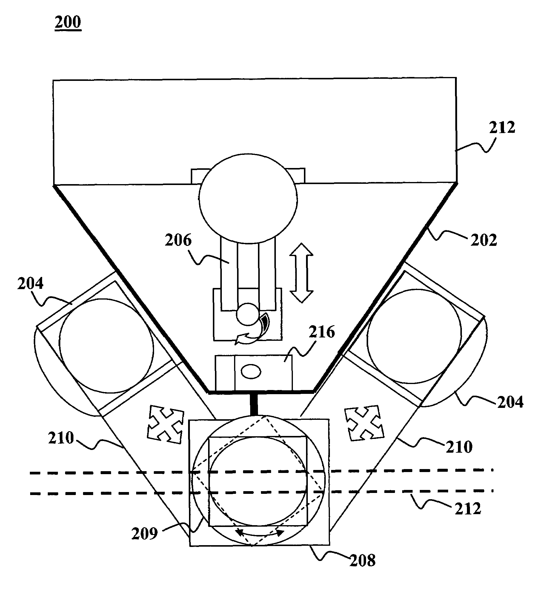
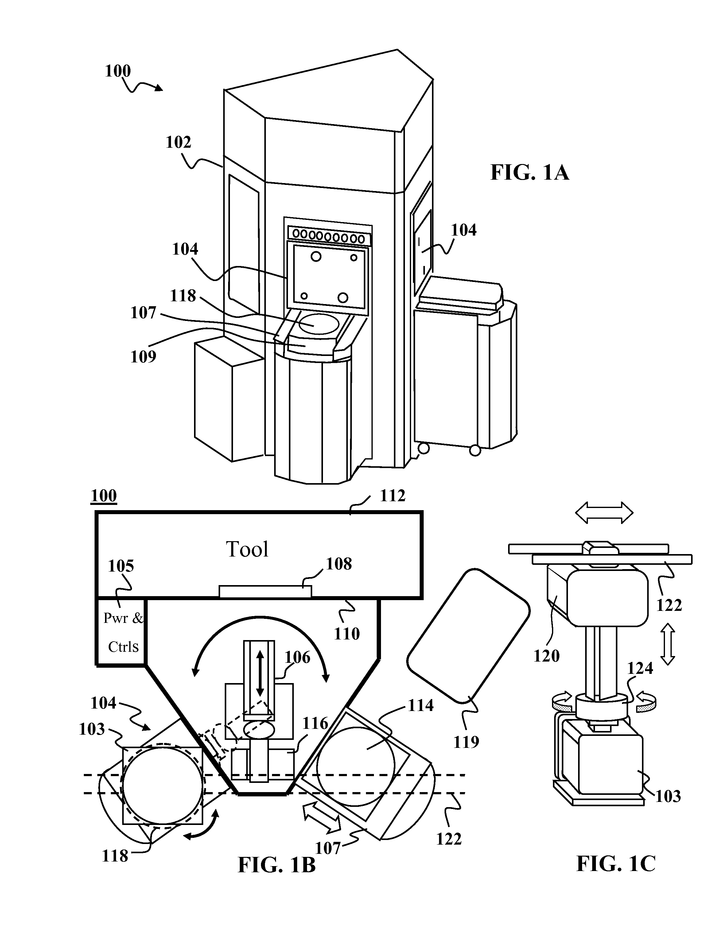
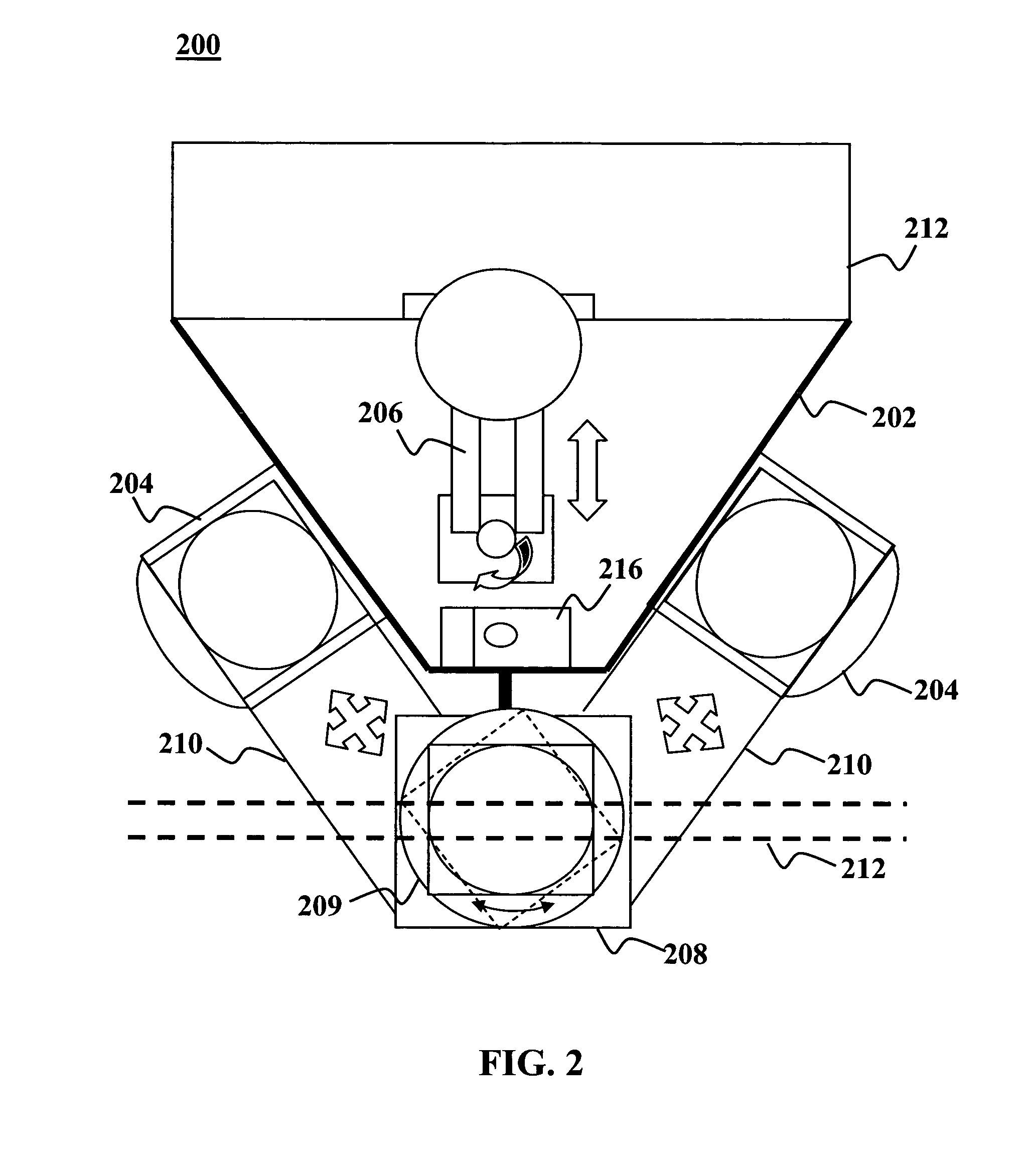
[0030]FIGS. 1A-1B depict an example of an EFEM system 100 according to an embodiment of the present invention. The system 100 generally includes an enclosure 102 having one or more front side walls. Two or more load ports 104 are built into the side walls. Each load port is conventionally configured to receive a front opening unified pod (FOUP) 103. For example, the load ports 104 may include a loading mechanism 107 having a moving shelf 109 that translates a FOUP toward or away from a door in the side wall. The load ports 104 are not arrang...


PUM


Abstract

Equipment front end module (EFEM) systems and methods for handling workpieces at EFEMs are disclosed. An equipment front end module (EFEM) system has an enclosure and a robot within the enclosure. The enclosure has two or more load ports, each being adapted to receive a front opening unified pod (FOUP). The robot is configured to move work pieces between the FOUP(s) and one or more work piece processing tools proximate the enclosure. The load ports are positioned relative to said robot such that said robot can move the work pieces between the tool and a FOUP at each load port with a simple R-theta motion or pure linear motion with respect to two axes.

Description

CROSS-REFERENCE TO RELATED APPLICATION[0001]This Application is related to commonly-assigned co-pending application Ser. No. 10 / 910,110, filed Jul. 29, 2004.FIELD OF THE INVENTION[0002]This invention generally relates to substrate processing and more particularly to equipment front end modules (EFEMs) used in substrate processing systems.BACKGROUND OF THE INVENTION[0003]Modern semiconductor fabrication facilities (known as “fabs”) use tools that can process multiple wafers. The wafers are typically delivered to a tool from a stocker in a front opening unified pod (FOUP). The FOUPS may be hand carried to and from the tool or they may be delivered by an automated material handling system (AHMS) or overhead track (OHT) system. Wafers are transferred from the FOUPs to the tool through an equipment front end module (EFEM). The EFEM typically includes one or more load ports (LPs) and robot arm that takes the wafers from a FOUP at a given load port and delivers them to the tool. Initially,...

Claims


Application Information

Patent Timeline
Patent Type & Authority Patents(United States)
IPC IPC(8): H01L21/677
CPCH01L21/67201H01L21/68707H01L21/67775H01L21/67766
Inventor KAVEH, FARROKH
Owner KLA TENCOR TECH CORP
Why Eureka
Try Eureka