Particulate corrosion resistant coating composition, coated turbine component and method for coating same

a technology of corrosion resistance coating and coating composition, which is applied in the field of particle corrosion resistance coating composition, coated turbine component and method for coating same, can solve the problems of premature removal and replacement pitting corrosion of critical turbine and increased concern for oxidation and corrosion of the disk/shaft and seal elements

Active Publication Date: 2009-10-20
GENERAL ELECTRIC CO
View PDF28 Cites 9 Cited by
  • Summary
  • Abstract
  • Description
  • Claims
  • Application Information

AI Technical Summary

Benefits of technology

[0046]The embodiments of the composition, article and method of this invention provide a number of significant benefits and advantages in providing corrosion resistant coatings on metal substrates for turbine components. These benefits and advantages include, but are not limited to: (1) minimizing or avoiding possible adverse affects on the fatigue life of the turbine disks / shafts and seal elements that the coating is applied to; (2) improving the strain tolerance of the coating to make the coating less prone to spalling; and (3) using less complicated and expensive processes (e.g., liquid spray techniques) for applying the corrosion resistant coating to the metal substrate.

Problems solved by technology

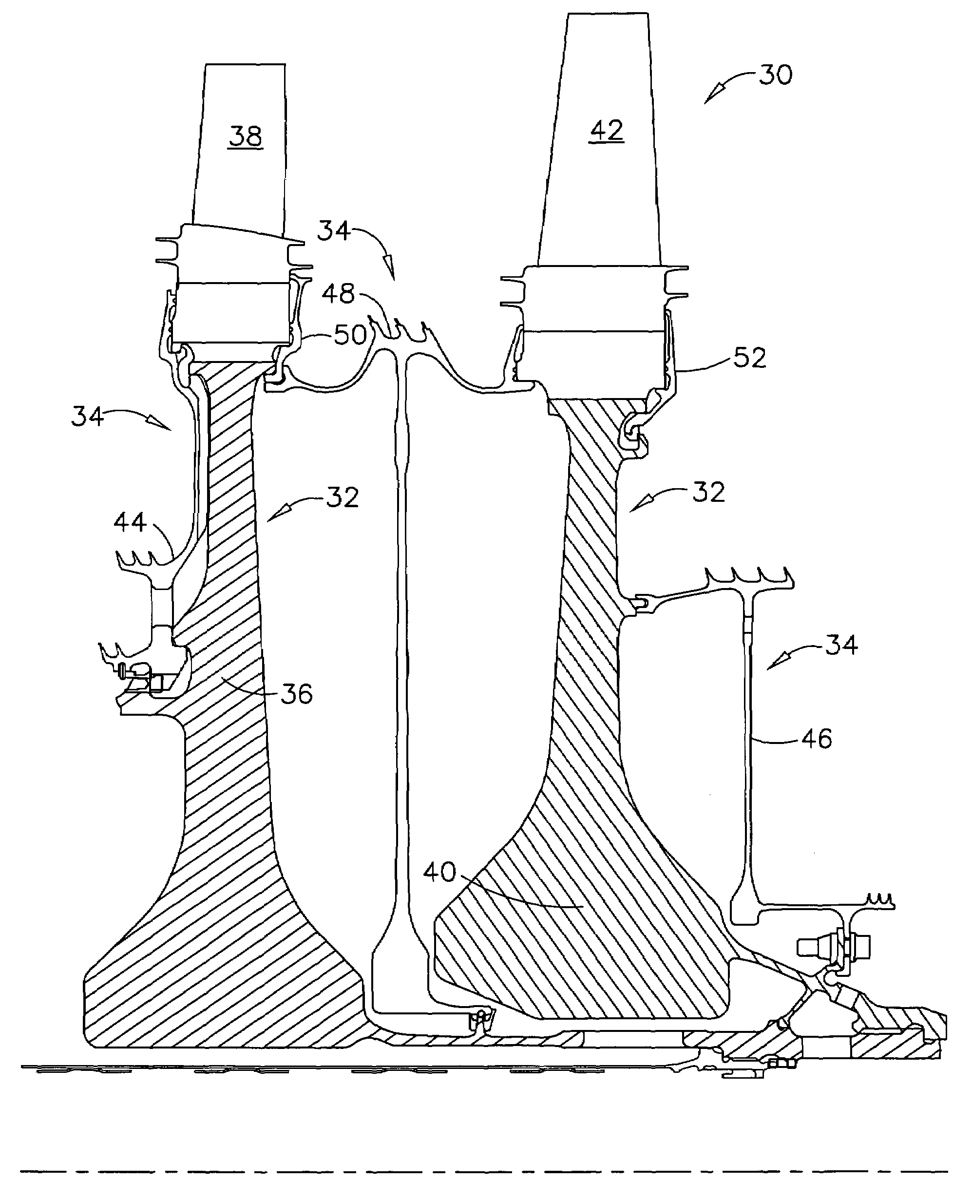
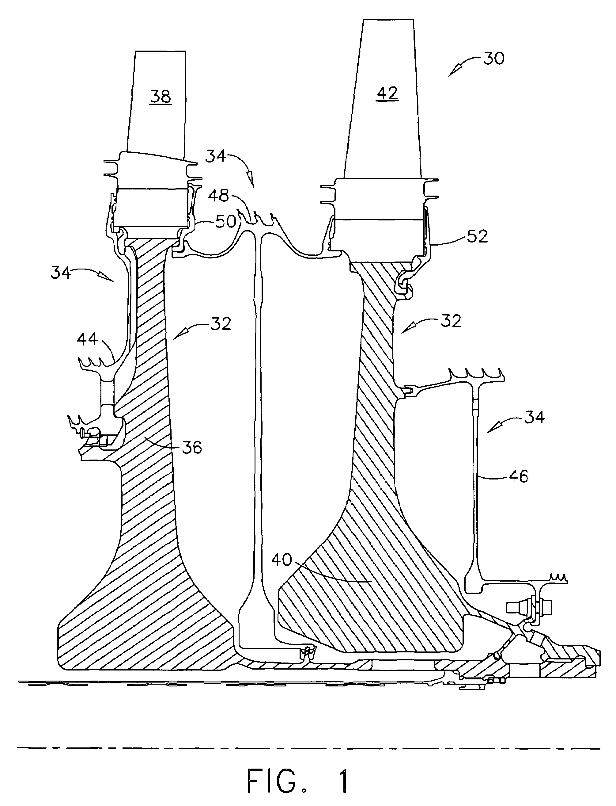
As a result, oxidation and corrosion of the disks / shafts and seal elements have become of greater concern.
Alkaline sulfate corrosion in the temperature range and atmospheric region of interest results in pitting of the turbine disk / shaft and seal element substrate at temperatures typically starting around 1000° F.
This pitting corrosion has been shown to occur on critical turbine disk / shaft and seal elements.
The oxidation and corrosion damage can lead to premature removal and replacement of the disks and seal elements unless the damage is reduced or repaired.
These superalloys have resistance to oxidation and corrosion damage, but that resistance may not be sufficient to protect them at sustained operating temperatures now being reached in gas turbine engines.
Disks and other rotor components made from newer generation alloys may also contain lower levels of chromium, and may therefore be more susceptible to corrosion attack.
While this delamination problem is most evident on the newer high performance gas turbine engines, this problem may also occur with other gas turbine engines because of the temperature extremes dictated by engine operation.

Method used


Image

  • Particulate corrosion resistant coating composition, coated turbine component and method for coating same
  • Particulate corrosion resistant coating composition, coated turbine component and method for coating same
  • Particulate corrosion resistant coating composition, coated turbine component and method for coating same

Examples


Embodiment Construction

[0051]As used herein, the term “particulate” refers to a particle, powder, flake, etc., that inherently exists in a relatively small form (e.g., a maximum particle size of about 62.5 microns or less, and typically a median ESD of about 25 microns or less) and may be formed by, for example, grinding, shredding, fragmenting, pulverizing, atomizing, or otherwise subdividing a larger form of the material into a relatively small form. Particulates useful in the corrosion resistant particulate components herein may have a maximum particle size in the range of from about 18.5 or less, to about 62.5 microns or less, and a maximum median particle size (as determined by the median ESD) in the range of from about 7.5 microns or less, to about 25 microns or less, more typically in the range of from about 3.8 microns or less, to about 12.5 microns or less. The maximum particle size of the particulates useful herein is primarily dependent on the CTEp thereof and is abbreviated herein as “Ap” and ...


PUM

PropertyMeasurementUnit
temperatureaaaaaaaaaa
temperaturesaaaaaaaaaa
thicknessesaaaaaaaaaa

Abstract

A composition comprising a glass-forming binder component and a particulate corrosion resistant component. The particulate corrosion resistant component comprises corrosion resistant particulates having: a CTEp of at least about 4 and being solid at a temperature of about 1300° F. (704° C.) or greater; and a maximum median particle size defined by one of the following formulas: (a) for a CTEp of 8 or less, an Mp equal to or less than (4.375×CTEp)−10; and (b) for a CTEp of greater than 8, an Mp equal to or less than (−4.375×CTEp)+60, wherein CTEp is the average CTE of the corrosion resistant particulates and wherein Mp is the median equivalent spherical diameter (ESD), in microns, of the corrosion resistant particulates. Also disclosed is an article comprising a turbine component comprising a metal substrate and a corrosion resistant coating overlaying the metal substrate, as well as a method for forming at least one layer of the corrosion resistant coating adjacent to the metal substrate. The corrosion resistant coating has a maximum thickness defined by one of the following formulas: (3) for a CTEp of 8 or less, an Tc equal to or less than (1.5×CTEp)−3.5; and (4) for a CTEp of greater than 8, an Tc equal to or less than (−1.5×CTEp)+20.5, wherein Tc is the thickness, in mils, of the corrosion resistant coating.

Description

BACKGROUND OF THE INVENTION[0001]This invention broadly relates to a corrosion resistant coating composition comprising a particulate corrosion resistant component, and a glass-forming binder component. This invention also broadly relates to an article comprising a turbine component coated with at least one layer of this composition. This invention further broadly relates to a method for coating the article with at least one layer of this composition.[0002]In an aircraft gas turbine engine, air is drawn into the front of the engine, compressed by a shaft-mounted compressor, and mixed with fuel. The mixture is burned, and the hot exhaust gases are passed through a turbine mounted on the same shaft. The flow of combustion gas turns the turbine by impingement against the airfoil section of the turbine blades, which turns the shaft and provides power to the compressor. The hot exhaust gases flow from the back of the engine, driving it and the aircraft forward. The hotter the combustion ...

Claims


Application Information

Patent Timeline
Patent Type & Authority Patents(United States)
IPC IPC(8): B32B15/04B32B9/00
CPCC03C1/006C03C1/008C03C8/08C03C8/14C23C24/08C23D5/00C23C22/74C03C2207/00Y10T428/12611Y02T50/67Y10T428/252Y10T428/26Y02T50/60
Inventor HAZEL, BRIAN THOMASWEIMER, MICHAEL JAMES
Owner GENERAL ELECTRIC CO
Why Eureka
Try Eureka