
Selective edge phase mixing

a technology of selective edge and phase mixing, applied in the direction of pulse manipulation, pulse technique, instruments, etc., can solve the problems of internal clock signal phase-shifted relative to external clock signal, various problems,

Active Publication Date: 2009-10-27
MICRON TECH INC
View PDF7 Cites 24 Cited by
  • Summary
  • Abstract
  • Description
  • Claims
  • Application Information

AI Technical Summary

Benefits of technology

The patent text describes a problem in synchronous integrated circuits where the internal clock signal may be phase-shifted relative to the external clock signal, causing difficulties in applying commands sent to the memory device by the processor. The text proposes various techniques for compensating for this problem, such as the use of a digital delay-locked loop (DLL) or phase-mixing techniques. However, these techniques have their limitations, such as the introduction of jitter and excessive heat generation. The invention provides apparatus and systems to compensate for duty cycle distortion in synchronous integrated circuits, overcoming the shortcomings of existing techniques.

Problems solved by technology

Since processing speeds can be much greater than memory access speeds, various operational difficulties may be encountered in exchanging information between the processor and the memory.
One significant problem the inventors have encountered in synchronous memory devices is that a time delay is introduced by circuitry within the memory device that causes the internal clock signal to be phase-shifted relative to the external clock signal.
As the frequency of the external clock is increased, however, differences between the external clock signal and the internal clock signal may become important, since even small differences between the external clock signals and the internal clock signals may prevent the proper application of commands sent to the memory by the processor.
Although the DLL is operable to provide some degree of synchronization, the inventors have discovered that various problems nevertheless exist.
For example, a principal component of the DLL is a delay chain that includes a plurality of serially coupled delay gates, which, together with other associated circuits, disadvantageously occupies a relatively large layout area.
Further, in order to achieve the desired synchronization, a large number of gates may be required, which disadvantageously introduces “jitter” into the clock signals.
Excessive amounts of heat may also be generated.
Another significant problem that the inventors have encountered as external clock signals increase involves undesired duty cycle variations.
Again, in cases where differences between the internal clock signal and the external clock signal are relatively insignificant, variations in duty cycle may, in turn, be relatively insignificant.
In extreme cases, if such duty cycle variations are left uncorrected, the memory device fails to operate properly.
Although this technique may provide the desired adjustment, the inventors have discovered that various problems nevertheless can exist.
For example, in certain cases, the phase-mixing fails to provide a sufficiently-wide range of adjustment.

Method used


Image

  • Selective edge phase mixing
  • Selective edge phase mixing
  • Selective edge phase mixing

Examples


Embodiment Construction

[0012]One technique for dealing with increasing operating speeds of systems is to employ synchronous integrated memory devices in the various digital systems. In general, synchronous integrated devices are synchronized by an applied clock signal, so that various operations may be performed at selected times. For example, the various operations may be synchronized with the rising and / or falling edges of the applied clock signal. Examples of such synchronous integrated memory devices may include synchronous dynamic random access memory (SDRAM) devices, synchronous static random access memory (SSRAM) devices, and may further include memory devices such as a synchronous link dynamic access memory (SLDRAM) devices, a RAMBUS dynamic random access memory (RDRAM), as well as other memory devices.

[0013]In particular, and with reference now to SDRAM, input and output latches are provided in the SDRAM to retain information that is to be transferred to, or from the controlling processor. For ex...


PUM


Abstract

Electronic apparatus, systems, and methods to implement selective edge phase mixing are disclosed. A selective edge phase mixing system includes a processor and memory device configured to perform operations in synchronization with transitions of an externally provided clock signal. A selective edge phase mixing unit for the memory device may include a first logic gate that receives the clock signal at an input port and receives first control signals, and pull-up circuits in communication with an output of the first logic gate and first control signals. A second logic gate receives the clock signal at the input port and receives second control signals. Pull-down circuits are coupled to the second logic gate and the second control signals, wherein the pull-up circuits and the pull-down circuits are coupled to the output port to provide a duty cycle corrected clock signal to the memory device. Additional apparatus, systems, and methods are disclosed.

Description

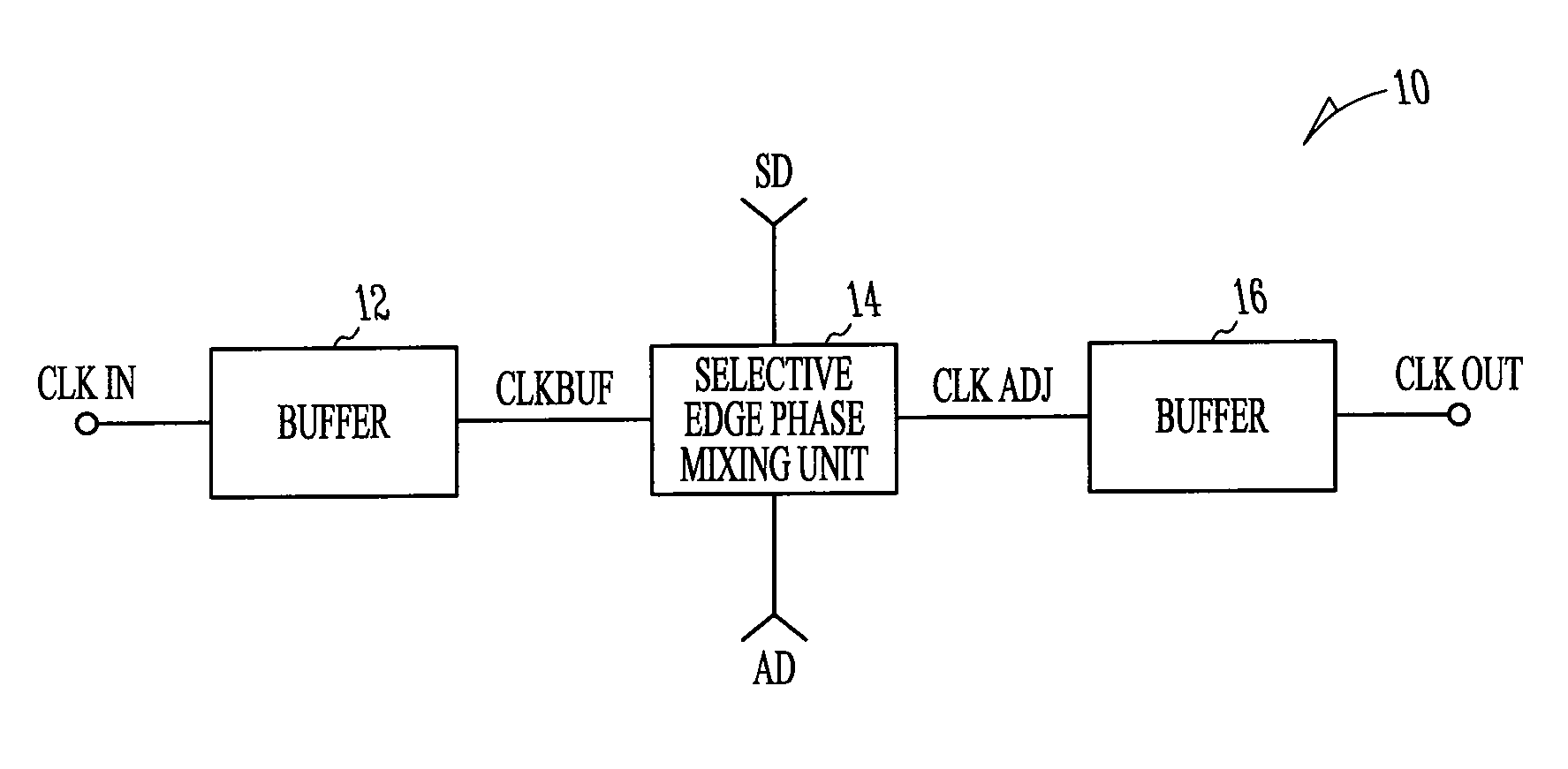
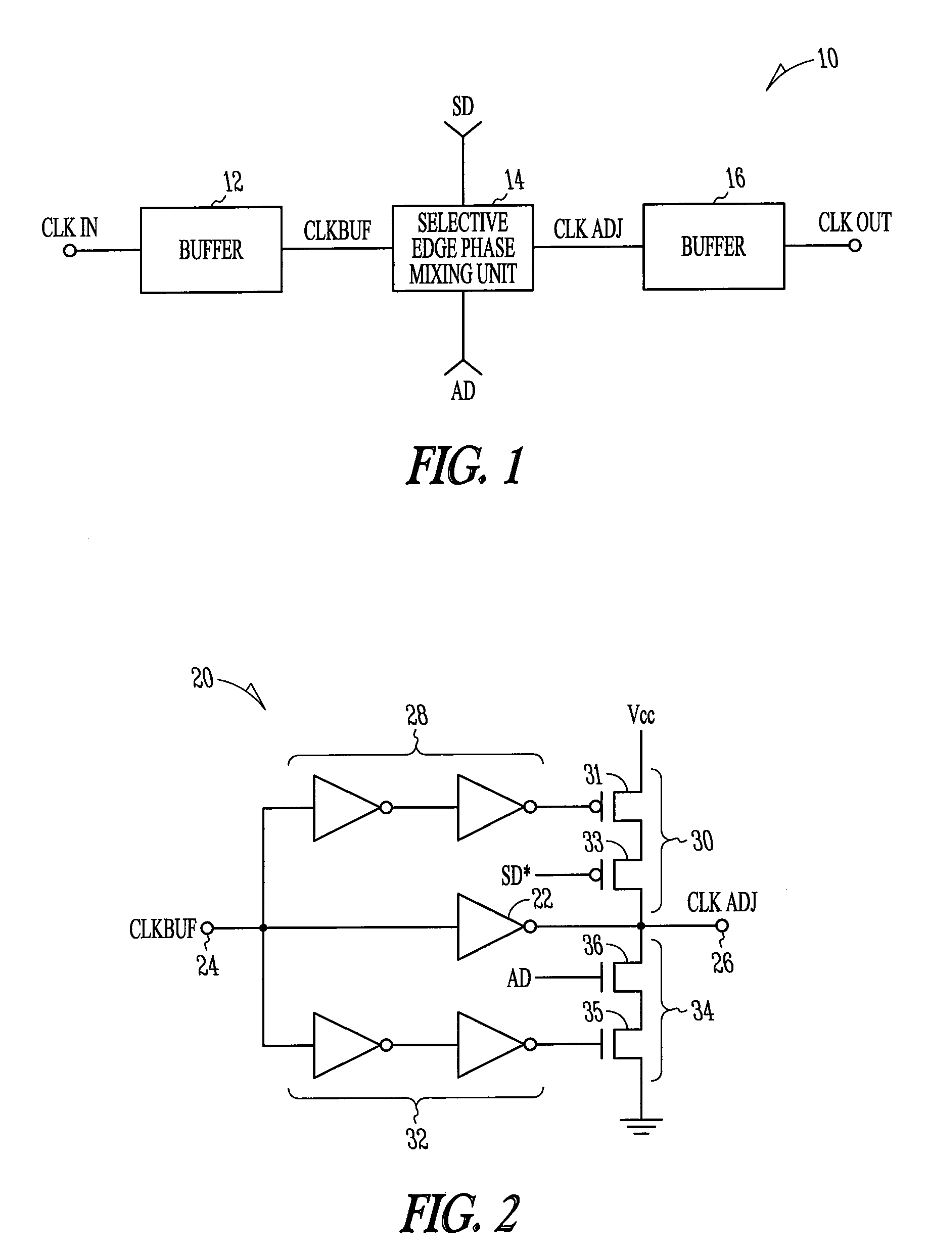
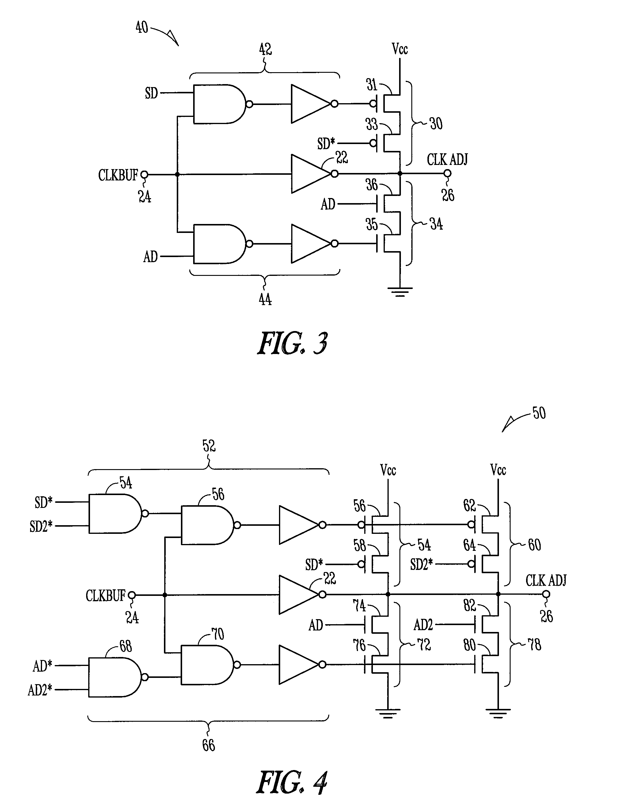
BACKGROUND[0001]Various systems, such as general-purpose computational devices, digital signal processors, video devices, and the like, include a high-speed memory system operable to store encoded instructions and data, and an attached processor that is configured to interpret and process the instructions. In general, the encoded instructions control the various processing operations of the processor, which can in turn access the data. Since processing speeds can be much greater than memory access speeds, various operational difficulties may be encountered in exchanging information between the processor and the memory.BRIEF DESCRIPTION OF THE DRAWINGS[0002]Various embodiments are described in detail in the discussion below, with reference to the following drawings.[0003]FIG. 1 is a diagrammatic block view of a selective edge phase mixing apparatus according to various embodiments.[0004]FIG. 2 is a schematic view of a selective edge phase mixing unit according to various embodiments....

Claims


Application Information

Patent Timeline
Patent Type & Authority Patents(United States)
IPC IPC(8): G11C8/00
CPCG11C7/22H03K5/1565G11C7/222
Inventor BOOTH, ERIC R.GOMM, TYLER J.
Owner MICRON TECH INC
Learn More