
System and method for behavior-based firewall modeling

a behavior-based firewall and behavior-based technology, applied in the field of network firewall designs and methodologies, can solve the problems of destructive or unauthorized access to data or operations of networked devices, firewalls are potentially complicated structures, and firewall owners must limit themselves to simple and inflexible features provided

Inactive Publication Date: 2009-10-27
RPX CORP
View PDF180 Cites 98 Cited by
  • Summary
  • Abstract
  • Description
  • Claims
  • Application Information

AI Technical Summary

Benefits of technology

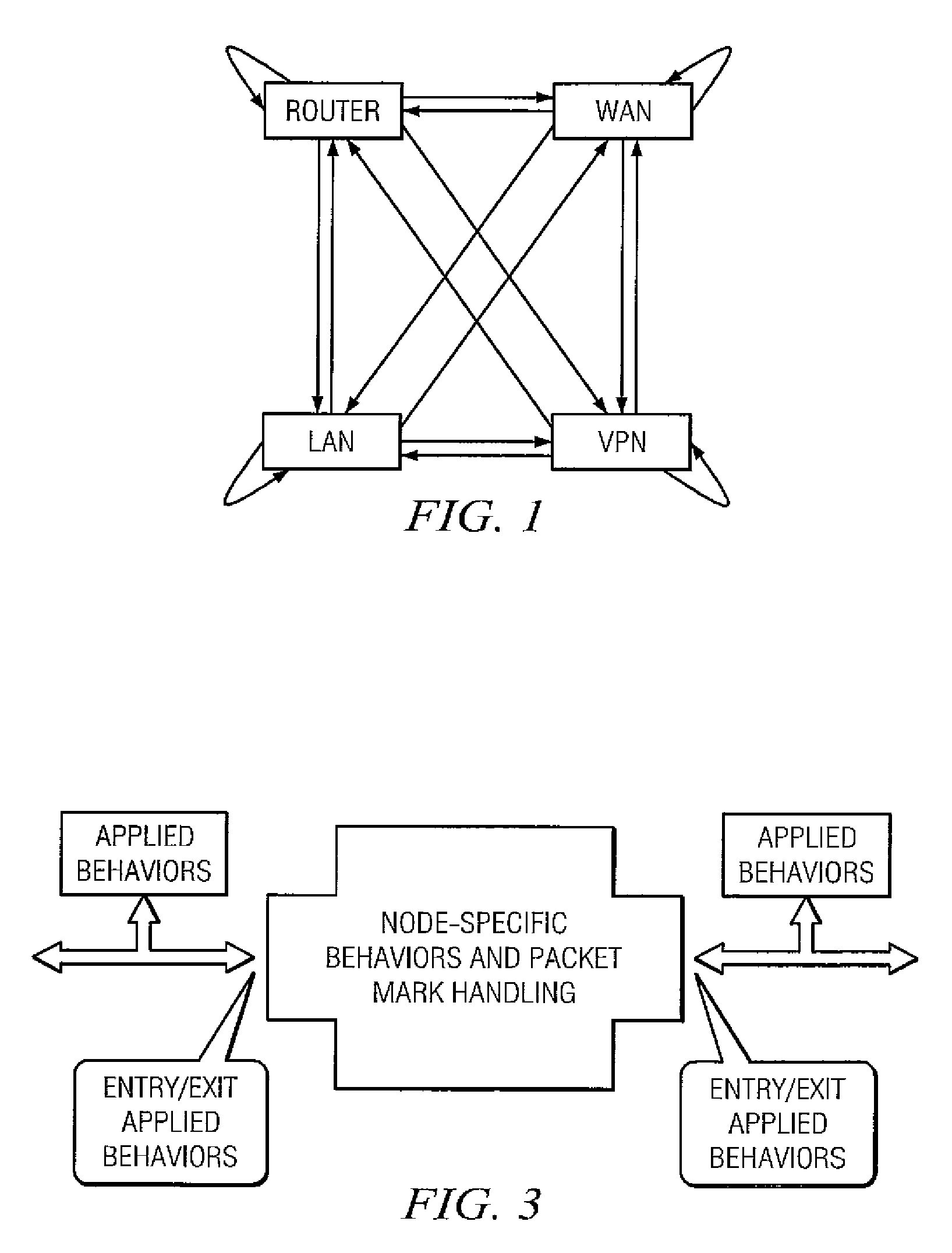
The current invention provides a new level of flexibility for firewalls, allowing them to automatically produce the necessary configuration based on the network client devices' needs. The firewall can dynamically add new network interface abstractions and tailor their behavior to the specific needs of each device. The invention models sources and destinations of network traffic as nodes with particular behaviors, and the connections between nodes also exhibit particular behaviors. The firewall can also react dynamically to changes in network interfaces, enabling the deployment of unsophisticated hardware and not requiring a custom platform.

Problems solved by technology

One unfortunate side effect is the evolution of destructive or unauthorized access to the data or operations of networked devices.
Firewalls are potentially complicated structures that are generally maintained manually by a skilled professional.
Firewall owners must therefore limit themselves to simple and inflexible features provided by typical network applications / devices, or they must invest in professionals who are skilled enough to construct and maintain firewalls to their specifications.
Previous firewall implementations are typically limited in two ways: (1) they are embedded in an inflexible hardware platform with no ability to expand and / or (2) they offer only a very simple set of user-visible features both because they have no expandability and because they lack the conceptual model to express more advanced features in a way that is convenient for customers to use.
These solutions are inadequate because they limit the power of the features available to customers.

Method used


Image

  • System and method for behavior-based firewall modeling
  • System and method for behavior-based firewall modeling
  • System and method for behavior-based firewall modeling

Examples


Embodiment Construction

[0021]The following applications are hereby fully incorporated by reference herein in their entirety: U.S. application Ser. No. 10 / 683,317, filed Oct. 10, 2003 entitled “SYSTEM AND METHOD FOR PROVIDING ACCESS CONTROL,” by Richard MacKinnon, Kelly Looney, and Eric White; U.S. Provisional Application No. 60 / 551,698, filed Mar. 10, 2004 entitled “SYSTEM AND METHOD FOR BEHAVIOR-BASED FIREWALL MODELING,” by Patrick Turley; U.S. Provisional Application No. 60 / 551,754, filed Mar. 10, 2004 entitled “SYSTEM AND METHOD FOR COMPREHENSIVE CODE GENERATION FOR SYSTEM MANAGEMENT,” by Keith Johnston which converted into U.S. application Ser. No. 11 / 078,223, filed Mar. 10, 2005 entitled “SYSTEM AND METHOD FOR COMPREHENSIVE CODE GENERATION FOR SYSTEM MANAGEMENT,” by Keith Johnston; U.S. Provisional Application No. 60 / 551,703, filed Mar. 10, 2004 entitled “SYSTEM AND METHOD FOR PROVIDING A CENTRALIZED DESCRIPTION / CONFIGURATION OF CLIENT DEVICES ON A NETWORK ACCESS GATEWAY,” by Patrick Turley and Keith...


PUM


Abstract

One embodiment of the present invention creates a model of the traffic through a network firewall and uses that model to dynamically manipulate the network firewall based on human intervention or based on the automatic invocations of processes and protocols that implement firewall policy. Another embodiment of the invention creates a model of the physical and virtual network interfaces that a firewall system controls and presents abstracted entities representing both the interface abstractions and the processing nodes (network segments or network client devices) to and through which network traffic flows.

Description

RELATED APPLICATIONS[0001]This application claims priority under 35 U.S.C. 119(e) to U.S. Provisional Patent Application No. 60 / 551,698, filed Mar. 10, 2004, entitled “SYSTEM AND METHOD FOR BEHAVIOR-BASED FIREWALL MODELING,” to Patrick Turley, which is hereby fully incorporated by reference herein.[0002]This application is also related to U.S. patent application Ser. No. 10 / 683,317, filed Oct. 10, 2003 entitled “SYSTEM AND METHOD FOR PROVIDING ACCESS CONTROL,” by Richard MacKinnon, Kelly Looney, and Eric White, and U.S. Provisional Patent Application No. 60 / 551,703, entitled “SYSTEM AND METHOD FOR PROVIDING A CENTRALIZED DESCRIPTION / CONFIGURATION OF CLIENT DEVICES ON A NETWORK ACCESS GATEWAY,” by Patrick Turley and Keith Johnston, filed Mar. 10, 2004 which are hereby fully incorporated by reference herein.TECHNICAL FIELD OF THE INVENTION[0003]Embodiments of the present invention relate generally to network firewall designs and methodologies and more specifically to network firewalls...

Claims


Application Information

Patent Timeline
Patent Type & Authority Patents(United States)
IPC IPC(8): H04L29/00H04L9/00
CPCH04L63/0263
Inventor TURLEY, PATRICKWHITE, ERIC
Owner RPX CORP
Learn More