Wound therapy device and related methods

a wound and therapy device technology, applied in the field of wound healing, can solve the problems of less able to successfully fight, difficult wound closure, diminished oxygen and nutrients, etc., and achieve the effect of closing wounds without stressing the surrounding skin

Inactive Publication Date: 2009-11-03
KCI LICENSING INC
View PDF154 Cites 330 Cited by
  • Summary
  • Abstract
  • Description
  • Claims
  • Application Information

AI Technical Summary

Benefits of technology

[0010]It is a primary object of the present invention to provide a wound closure apparatus that closes wounds without stressing the surrounding skin.

Problems solved by technology

Unfortunately, closure is difficult with large wounds or wounds that have become infected.
Without sufficient blood flow, the epithelial and subcutaneous tissues surrounding the wound not only receive diminished oxygen and nutrients, but are also less able to successfully fight bacterial infection and, thus are less able to close the wound naturally.
Such wounds have presented difficulties to medical personnel for many years.
Although such mechanical closure techniques are widely practiced and often effective, they suffer a major disadvantage by providing tension on the skin tissue adjacent the wound.
That is, the tensile force required to achieve closure using sutures or staples causes very high localized stresses at the suture or staple insertion point.
Such stresses commonly result in the rupture of the tissue at those points, which can eventually cause dehiscence in wounds, providing additional tissue loss.
Moreover, some wounds harden and inflame to such a degree due to infection that closure by stapling or suturing is not feasible.
Wounds not reparable by suturing or stapling generally require prolonged hospitalization, with its attendant high cost, and major surgical procedures, such as grafts of surrounding tissues.
One problem with the apparatus described in the above prior document is that no means are disclosed for avoiding spread of infection from one patient to another or re-infection of the patient being treated.

Method used


Image

  • Wound therapy device and related methods
  • Wound therapy device and related methods
  • Wound therapy device and related methods

Examples


Embodiment Construction

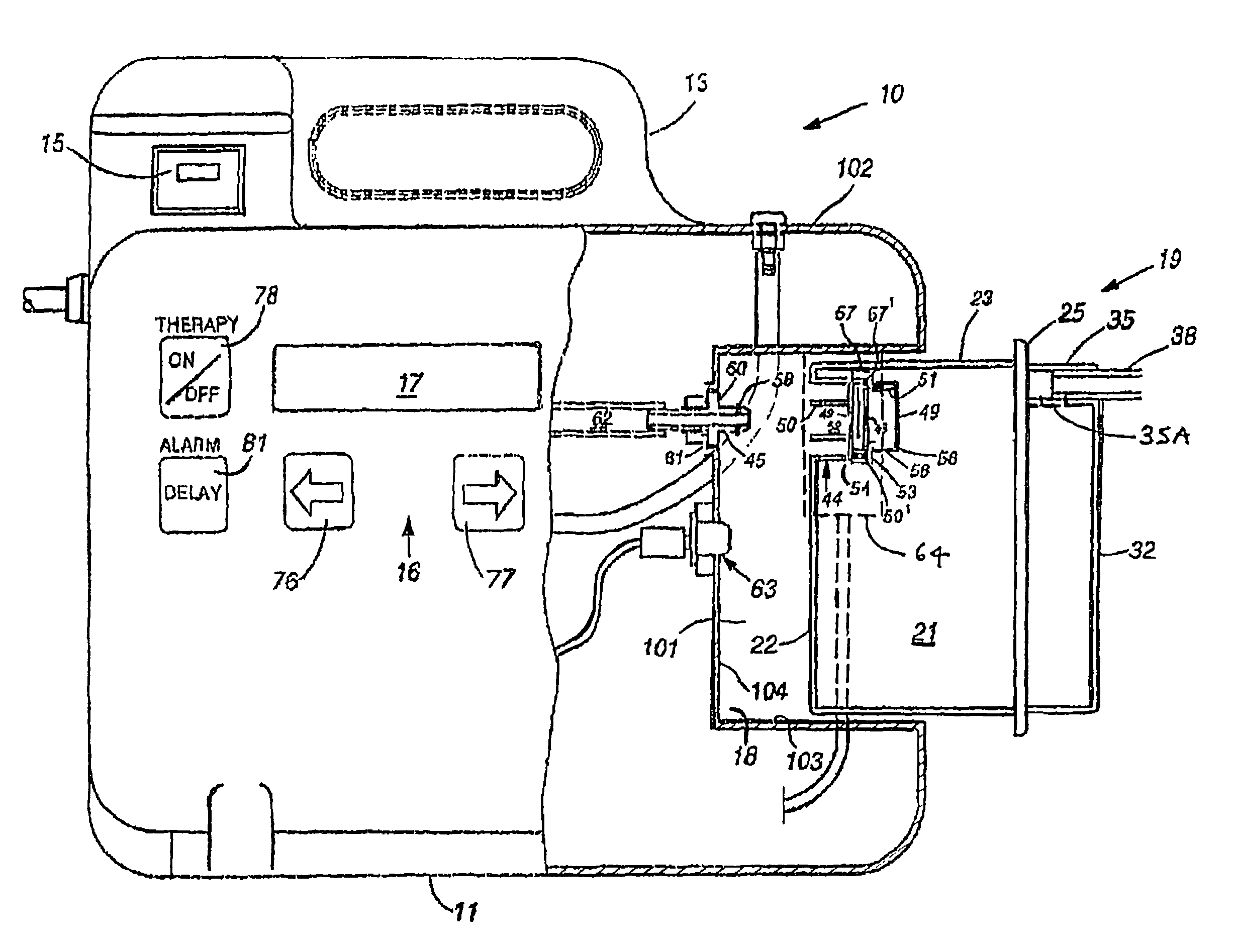
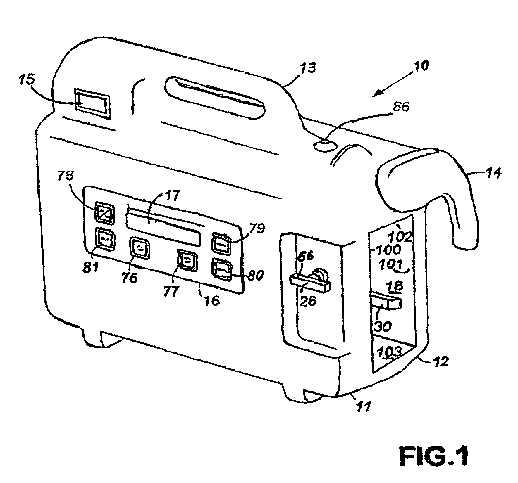
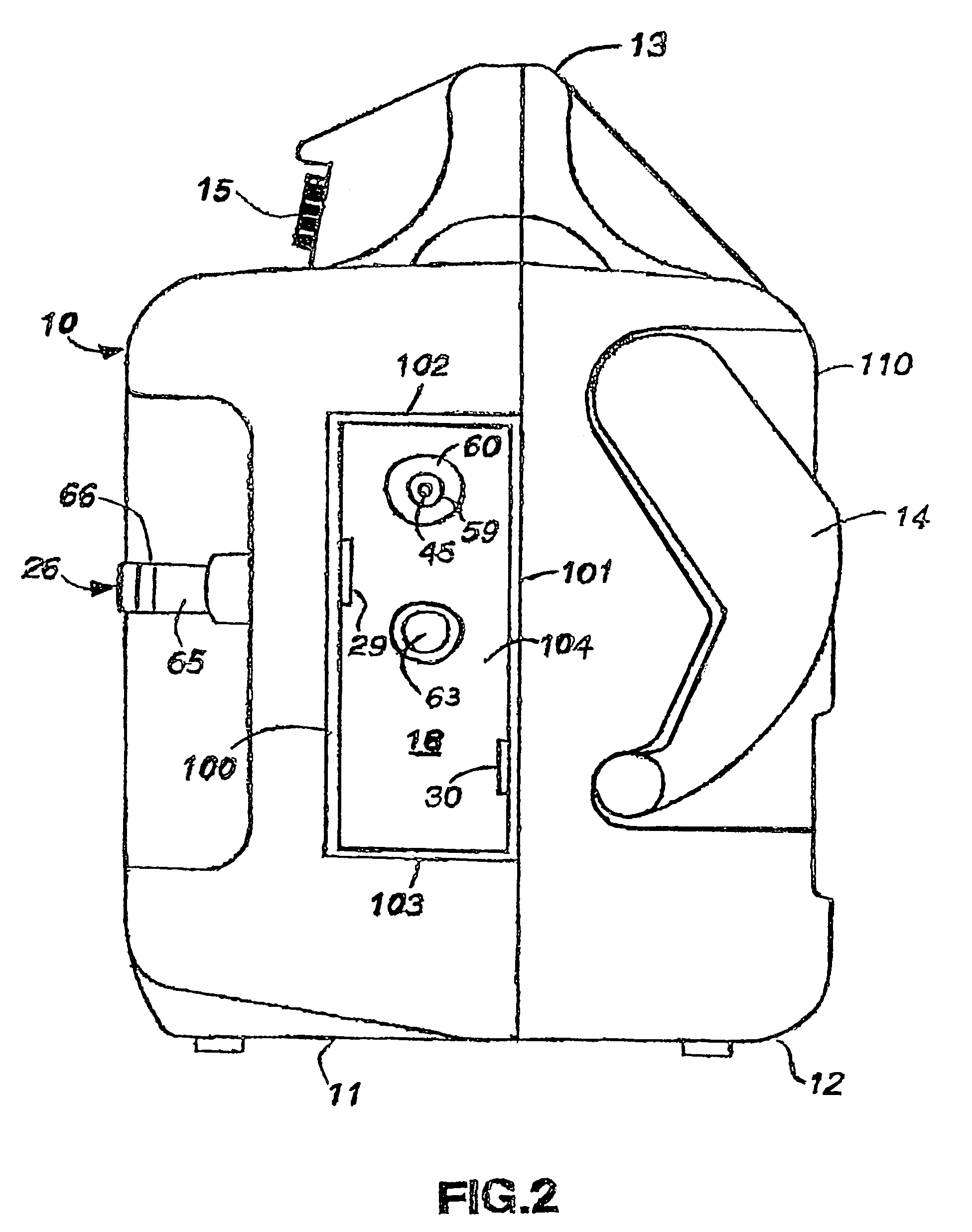
[0028]As illustrated in FIGS. 1 and 2, front housing 11 and rear housing 12 connect together using any suitable means such as screws and fasteners to provide wound closure vacuum pump 10 with a small, compact, and easily portable carrying case. Consequently, front housing 11 and rear housing 12 connect together to form handle 13 that permits easy carrying of wound closure apparatus 10. Except as may be otherwise evident from this description, the carrying case of vacuum pump 10 is substantially as described and shown in WIPO Design No. DM / 032185.

[0029]Front housing 11 includes power switch 15 that is movable between an on and off position to permit user control of the delivery of power to wound closure apparatus 10. Keypad 16 and liquid crystal display (LCD) 17 mount to front housing 11 to permit the programming of wound closure apparatus 10. Chamber 18 is defined by integrally formed interior side walls 100 and 101, top wall 102, bottom wall 103 and rear wall 104. Side wall 100 is ...


PUM


Abstract

A wound closure apparatus is disclosed which includes a housing that contains a vacuum pump and a chamber for holding a disposable wound fluid collection canister. The canister resides within the chamber and connects at an outlet with the vacuum pump and at an inlet with a pad. The pad is placed over a wound and adhesively secured thereto. When the vacuum pump activates, it evacuates air from the canister resulting in wound fluids flowing from the wound into the canister. After the canister is filled, it is removed from the chamber and replaced with another canister to continue the removal of wound fluids.

Description

[0001]This application is a continuation of application Ser. No. 08 / 517,901 filed Aug. 22, 1995; now abandoned which is a continuation-in-part of application Ser. No. 08 / 293,854 filed Aug. 22, 1994 now abandoned.BACKGROUND OF THE INVENTION[0002]1. Field of the Invention[0003]The present invention relates to the healing of wounds and, more particularly, but not by way of limitation, to an apparatus for closing wounds that is compact, self-contained, and includes a disposable wound fluids canister.[0004]2. Description of Background Art[0005]Wound closure involves epithelial and subcutaneous tissue adjacent the wound migrating towards the center of the wound until it closes. Unfortunately, closure is difficult with large wounds or wounds that have become infected. In such wounds, a zone of stasis (i.e. an area in which localized swelling of tissue restricts the flow of blood to the tissues) forms near the surface of the wound. Without sufficient blood flow, the epithelial and subcutane...

Claims


Application Information

Patent Timeline
Patent Type & Authority Patents(United States)
IPC IPC(8): A61F13/00A61F13/02A61M1/06A61M1/00A61M27/00
CPCA61M1/0096A61M1/0037A61M1/0088A61M27/00A61M1/0052A61M1/0023A61M1/0001A61M1/0031A61M2205/123A61M2205/14A61M2205/17A61M2205/18A61M2205/3317A61M2205/3382A61M2205/7518A61M2209/086A61M1/75A61M1/784A61M1/882A61M1/74A61M1/71A61M1/96A61M1/732A61M1/982A61M1/78A61M1/60A61M1/72
Inventor LINA, CESAR Z.HEATON, KEITH
Owner KCI LICENSING INC
Why Eureka
Try Eureka