
Optical FM source based on intra-cavity phase and amplitude modulation in lasers

a laser and optical fm technology, applied in the field of semiconductor laser diodes, can solve the problems of pattern dependence, low fm generation efficiency, slow time scale from lasing frequency to red shift to lower frequencies, etc., to reduce or eliminate thermal chirp within the laser, increase the fm efficiency of the system, and increase the adiabatic chirp

Inactive Publication Date: 2009-11-03
II VI DELAWARE INC
View PDF83 Cites 22 Cited by
  • Summary
  • Abstract
  • Description
  • Claims
  • Application Information

AI Technical Summary

Benefits of technology

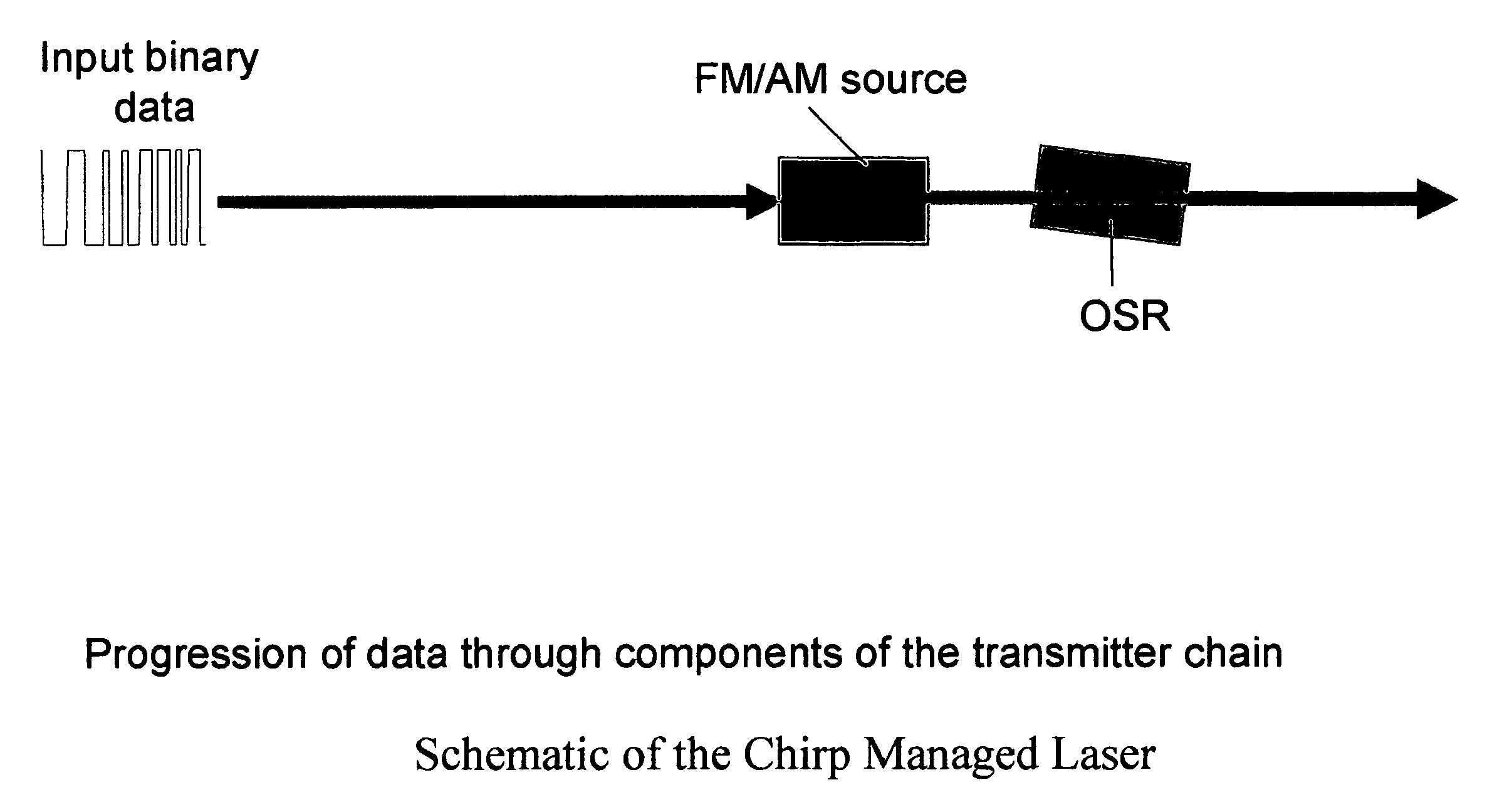
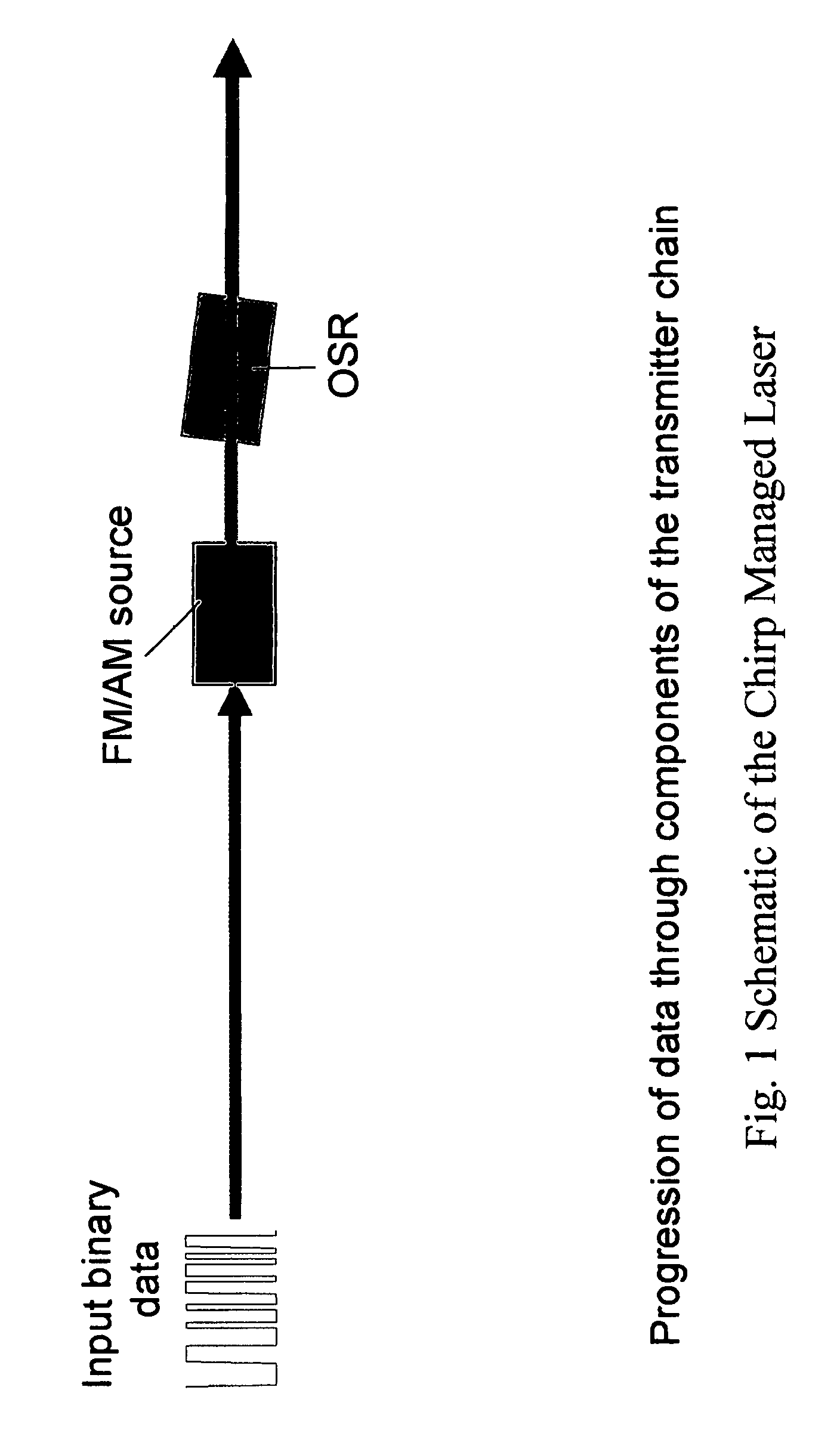
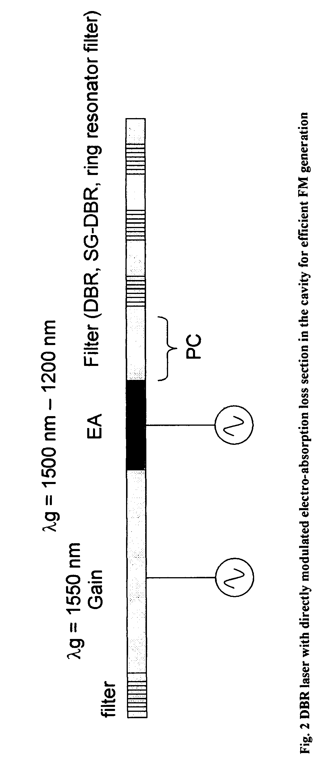
[0017]The present invention provides an optical frequency modulated (FM) source based on intra-cavity phase and amplitude modulation in lasers. And in one form of the present invention, this FM source may be used in a CML transmitter. More particularly, in one preferred form of the present invention, there is provided (i) a chirp managed laser (CML) comprising an FM source, and (ii) an optical spectrum reshaper (OSR) filter, wherein the desired FM is generated using intra-cavity loss modulation of the laser cavity. This approach for FM generation can be applied to a variety of laser designs, and a variety of methods can be used to modulate the loss of the cavity. In one preferred embodiment of the present invention, the laser is a distributed Bragg reflector (DBR) laser, and the loss of the laser cavity is directly modulated by an electro-absorption (EA) modulator, which is integrated in the laser cavity. Modulation of the cavity loss causes the carrier density in the gain section to change significantly, thereby generating large adiabatic chirp. This approach is highly advantageous, since it substantially reduces or eliminates thermal chirp within the laser, thereby increasing the FM efficiency of the system. This can provide a substantial improvement to the aforementioned CML systems.

Problems solved by technology

However, this method of FM generation is very inefficient.
Furthermore, FM modulation by gain modulation through current injection leads to the heating of laser cavity, which in turn causes the lasing frequency to red shift to lower frequencies on a slow time scale.
Thermal chirp can generate pattern dependence and can increase the bit error rate (BER) of a digital transmission system such as a chirp managed laser (CML) transmitter.
On the other hand, directly modulated lasers (DML) typically reach <5 km because their inherent time-dependent chirp causes severe distortion of the signal after this distance.

Method used


Image

  • Optical FM source based on intra-cavity phase and amplitude modulation in lasers
  • Optical FM source based on intra-cavity phase and amplitude modulation in lasers
  • Optical FM source based on intra-cavity phase and amplitude modulation in lasers

Examples


Embodiment Construction

[0044]FIG. 2 shows one preferred embodiment of the present invention, wherein an electro-absorption (EA) modulator is integrated inside a distributed Bragg reflector (DBR) laser cavity. The EA section is reverse biased. Application of a reverse bias voltage to the EA increases cavity loss, which increases the threshold gain for lasing. This increases the threshold carrier density, which causes the laser frequency to shift towards the blue, i.e., so as to provide frequency modulation.

[0045]The large FM efficiency by loss modulation can be understood by considering FIG. 3, which shows the lasing wavelength as a function of injection current into a constant wave (CW) laser. It is known that the lasing wavelength of a CW semiconductor laser depends on the threshold current. Wavelength shifts to the blue as more carriers are injected into the laser below threshold. For example, the wavelength of the laser shifts by 0.2 nm (24 GHz) when the threshold current increases from 7 mA to 9 mA. T...


PUM


Abstract

A fiber optic communication system comprising:an optical signal source adapted to receive a binary base signal having a bit period T, and generate a first signal, wherein the first signal is frequency modulated; andan optical spectrum reshaper (OSR) adapted to reshape the first signal into a second signal, wherein the second signal is amplitude modulated and frequency modulated;characterized in that:the optical signal source is a laser in which frequency modulation is generated by modulating the loss of the laser cavity.A method for transmitting a signal, comprising:receiving a binary base signal having a bit period T, and generating a first signal, wherein the first signal is frequency modulated; andreshaping the first signal into a second signal, wherein the second signal is amplitude modulated and frequency modulated;characterized in that:the first signal is frequency modulated by using a laser in which frequency modulation is generated by modulating the loss of the laser cavity.A fiber optic communication system comprising:an optical signal source adapted to receive a binary base signal having a bit period T, and generate a first signal, wherein the first signal is frequency modulated; andan optical spectrum reshaper (OSR) adapted to reshape the first signal into a second signal, wherein the second signal is amplitude modulated and frequency modulated;characterized in that:the optical signal source is a laser in which frequency modulation is generated by modulating the phase of the laser cavity.

Description

REFERENCE TO PENDING PRIOR PATENT APPLICATIONS[0001]This patent application:[0002](i) is a continuation-in-part of pending prior U.S. patent application Ser. No. 11 / 272,100, filed Nov. 8, 2005 by Daniel Mahgerefteh et al. for POWER SOURCE FOR A DISPERSION COMPENSATION FIBER OPTIC SYSTEM;[0003](ii) is a continuation-in-part of pending prior U.S. patent application Ser. No. 10 / 308,522, filed Dec. 3, 2002 by Daniel Mahgerefteh et al. for HIGH-SPEED TRANSMISSION SYSTEM COMPRISING A COUPLED MULTI-CAVITY OPTICAL DISCRIMINATOR;[0004](iii) is a continuation-in-part of pending prior U.S. patent application Ser. No. 11 / 441,944, filed May 26, 2006 by Daniel Mahgerefteh et al. for FLAT DISPERSION FREQUENCY DISCRIMINATOR (FDFD);[0005](iv) is a continuation-in-part of pending prior U.S. patent application Ser. No. 11 / 037,718, filed Jan. 18, 2005 by Yasuhiro Matsui et al. for CHIRP MANAGED DIRECTLY MODULATED LASER WITH BANDWIDTH LIMITING OPTICAL SPECTRUM RESHAPER;[0006](v) is a continuation-in-par...

Claims


Application Information

Patent Timeline
Patent Type & Authority Patents(United States)
IPC IPC(8): H04B10/04
CPCH04B10/505H04B10/516H04B10/541H04B10/5563H04B10/5161H04B2210/517
Inventor MATSUI, YASUHIROTAYEBATI, PARVIZMAHGEREFTEH, DANIEL
Owner II VI DELAWARE INC
Learn More