Ultrasound flow sensor with a modulo-2Pi for a remaining part tracing
- Summary
- Abstract
- Description
- Claims
- Application Information
AI Technical Summary
Benefits of technology
Problems solved by technology
Method used
Image
Examples
Embodiment Construction
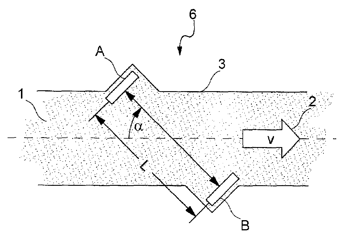
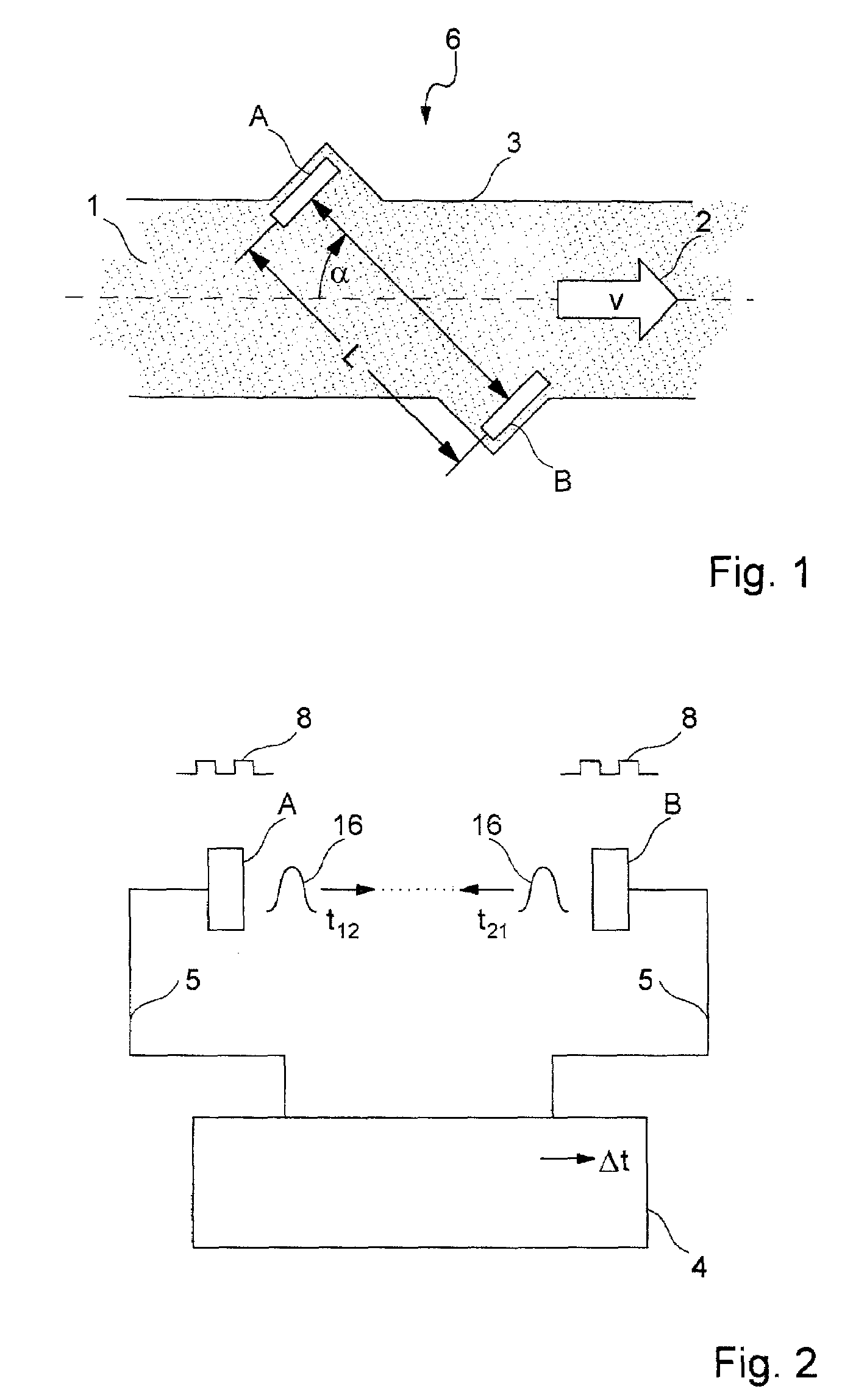
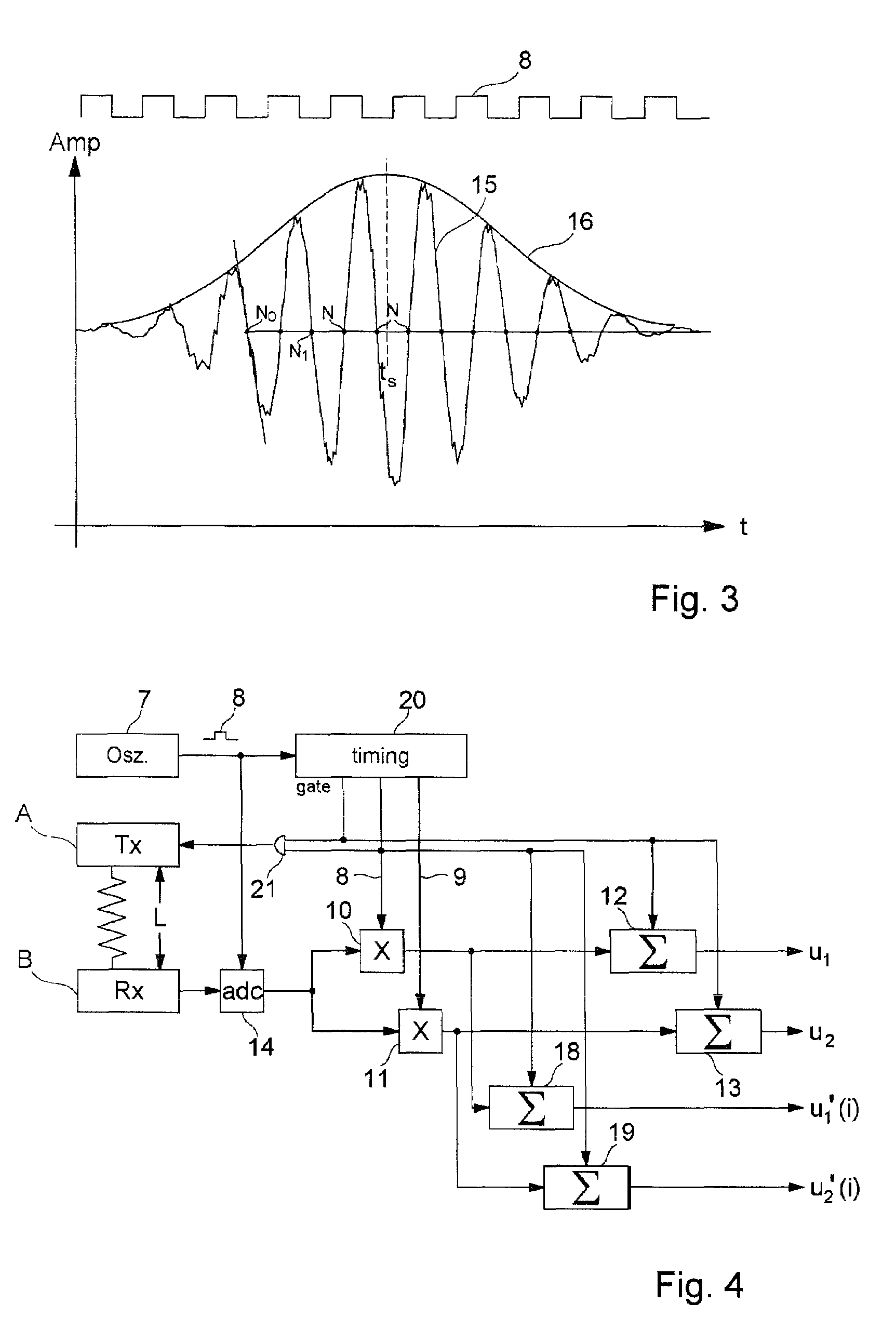
[0030]FIGS. 1 through 3 are explained in the introduction of the description.
[0031]FIG. 4 shows an embodiment of an ultrasonic flow sensor 6 with two ultrasonic converters A, B and control and evaluation electronics 4. Electronics 4 include an oscillator 7 that generates a timing signal 8, with which converters A, B are excited. As a result, both converters A generate ultrasonic signals 15, which are transmitted to the other converter, where they are detected. Based on transit time t12 of a signal 15 in one direction, and transit time t21 in the other direction, it is then possible to calculate the flow rate v or mass flow of flowing medium 1.
[0032]Transit time t of an ultrasonic signal 15 can also be depicted as a phase, i.e.:
t˜n·2pi+Δφ
or
t˜r(t)+Δφ
[0033]Here, Δφ is the phase angle of received ultrasonic signal 15 relative to a reference timing signal 8, and n·2 pi and r(t) are the remainder of the entire phase; n is the number of complete wave trains within transit time t.
[0034]In t...
PUM
 Abstract
Description
Claims
Application Information
 - R&D
- Intellectual Property
- Life Sciences
- Materials
- Tech Scout
- Unparalleled Data Quality
- Higher Quality Content
- 60% Fewer Hallucinations
Browse by: Latest US Patents, China's latest patents, Technical Efficacy Thesaurus, Application Domain, Technology Topic, Popular Technical Reports.
© 2025 PatSnap. All rights reserved.Legal|Privacy policy|Modern Slavery Act Transparency Statement|Sitemap|About US| Contact US: help@patsnap.com


