Umbrella base with power supply

a power supply and umbrella technology, applied in the field of umbrellas, can solve the problems of inability to easily see advertisements by people close, inconvenient placement of batteries, and inconvenient use, so as to facilitate the placement of batteries, facilitate the distribution of ballast materials, and minimize the shifting of ballast materials

Inactive Publication Date: 2009-11-10
ROLLING UMBRELLAS INC
View PDF44 Cites 102 Cited by
  • Summary
  • Abstract
  • Description
  • Claims
  • Application Information

AI Technical Summary

Benefits of technology

[0017]In another aspect of the invention, the body portion of the umbrella base is comprised of a ballast housing assembly which includes a lower ballast holding portion (sometimes referred to herein as “lower housing”) having at least one ballast cavity in which the power source is located, and which, can otherwise be filled with a ballast material, such as water, sand, steel shot, iron, lead, concrete, cement. The housing assembly further includes a top cover portion (sometimes referred to as “housing cover”) that removably fits onto the lower portion of the housing assembly to cover the at least one ballast cavity. The removable cover portion provides access to the ballast cavity without the need for narrow fill openings for the ballast material, and permits aggregate ballast materials such as sand or cement to be distributed evenly within the cavity. The ballast cavity is optionally divided into smaller cavities such as by partition walls disposed in the cavity. Multiple cavities facilitate even distribution of the ballast material within the lower ballast holding portion of the housing and minimize shifting of the ballast material within the base when the base is moved or tipped. They also facilitate the placement of batteries or other power supplies in the ballast cavities, and possibly the use of other relatively small easy to handle ballast containers sized and shaped to fit within the cavities. Specific cavity volumes can also be provided to predetermine the amount of ballast weight that will be added for a given ballast material.

Problems solved by technology

Heretofore, such advertising has been limited to imprinting or otherwise incorporating company names, product names, logos and the like directly on the umbrella's fabric covering, where the advertising is within normal sight lines of persons situated at a distance from the umbrella, however, where the advertising cannot be easily viewed by persons close in, such as persons seated under the umbrella.
Weight is an important issue for patio umbrella bases.
Too much weight is undesirable because the base would be excessively heavy and difficult to move.
The added weight may also lead to increased shipping costs.
Insufficient weight would make the umbrella susceptible to being toppled by wind or other forces.
Such weight is adequate to support some patio umbrellas in some environments, however, it may be inadequate depending on weather conditions and the umbrella size.
Also, metal bases are susceptible to corrosion which results not only in the deterioration of its outer appearance, but also creates a problem when rust particles stain the surrounding support surfaces such as wood or concrete.
Protective coatings such as rust resistant paint and even high cost powder coatings have been used to help alleviate this problem, however, in high traffic areas repeated contact with tables and chairs can cause scratches in the surface coatings allowing the metal beneath the protected surface to rust.
Such bases are heavy, unattractive and difficult to move, and not well adapted for many use environments.
This molding process produces low cost, rust resistant parts, however, the parts generally are large and bulky and cosmetically unattractive.
Also, they are produced with a relatively thin and uniform wall thickness making it difficult to attach the necessary structural tubing to hold the umbrella shaft.
Once filled, they are very difficult to move without the draining of the fluid ballast.
The difficulty in moving conventional umbrella bases is a significant drawback.
However, because of the difficulty in moving existing umbrella bases and because the offset angle of the umbrella only offers minimal shade adjustments, users usually need to move their table and chairs to the new shaded area as the day progresses.
This can create a dangerous situation due to the traffic, tables and chairs that surround each umbrella base where people can trip or possibly damage the electrical cord.
In addition, many umbrellas are used around water sources such as pools, pond, lakes etc. that could cause serious, if not deadly, results if the umbrella was tipped or blown over into the water source causing an electrical hazard.

Method used


Image

  • Umbrella base with power supply
  • Umbrella base with power supply
  • Umbrella base with power supply

Examples


Embodiment Construction

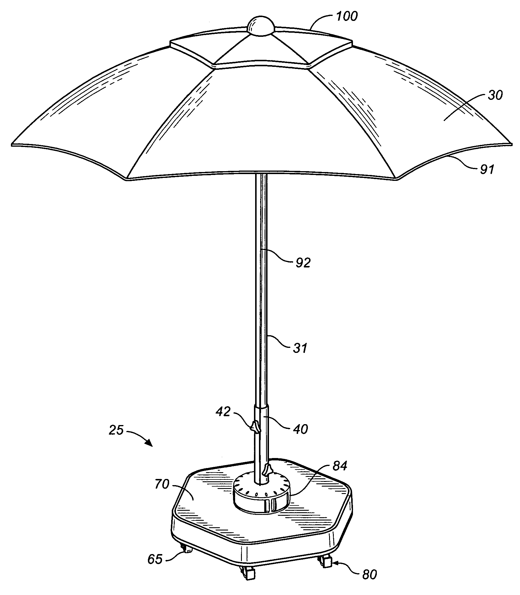
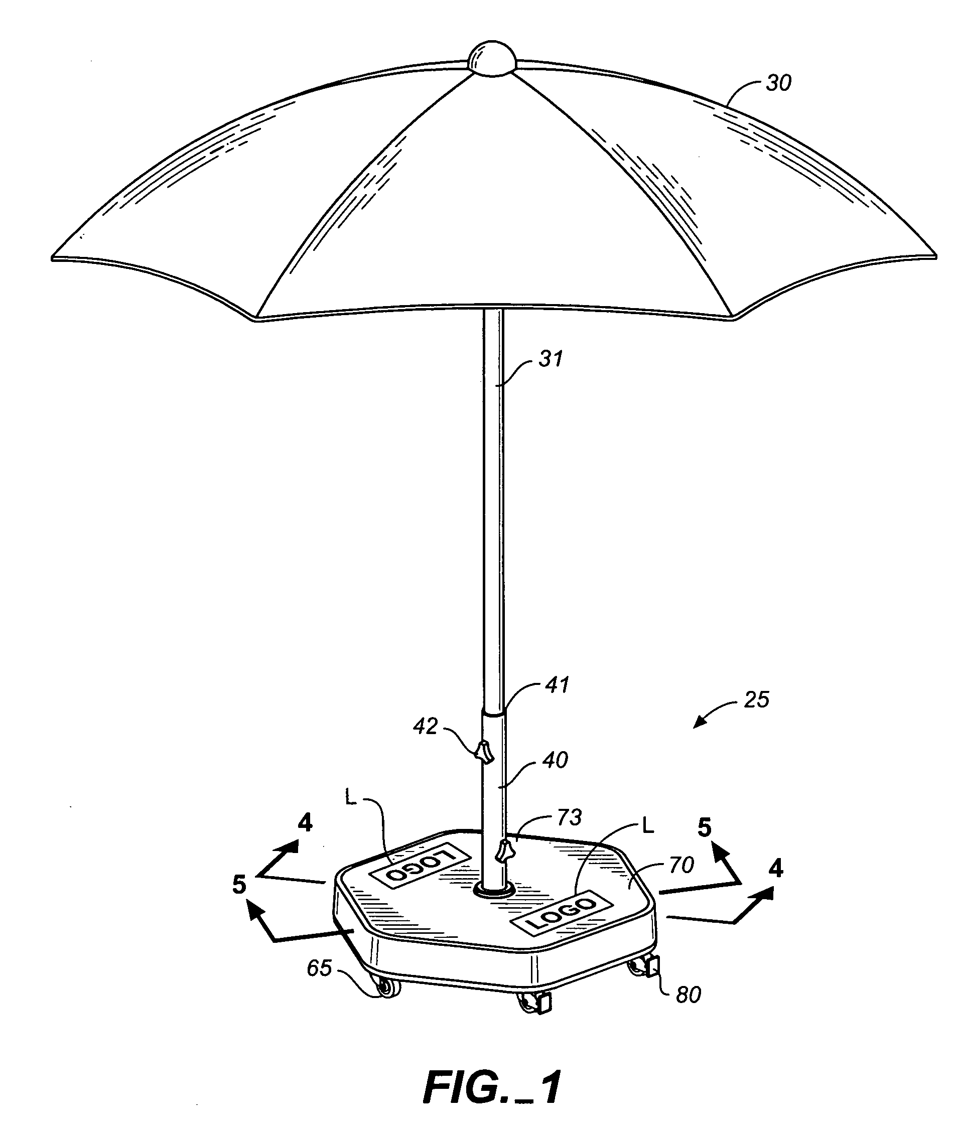
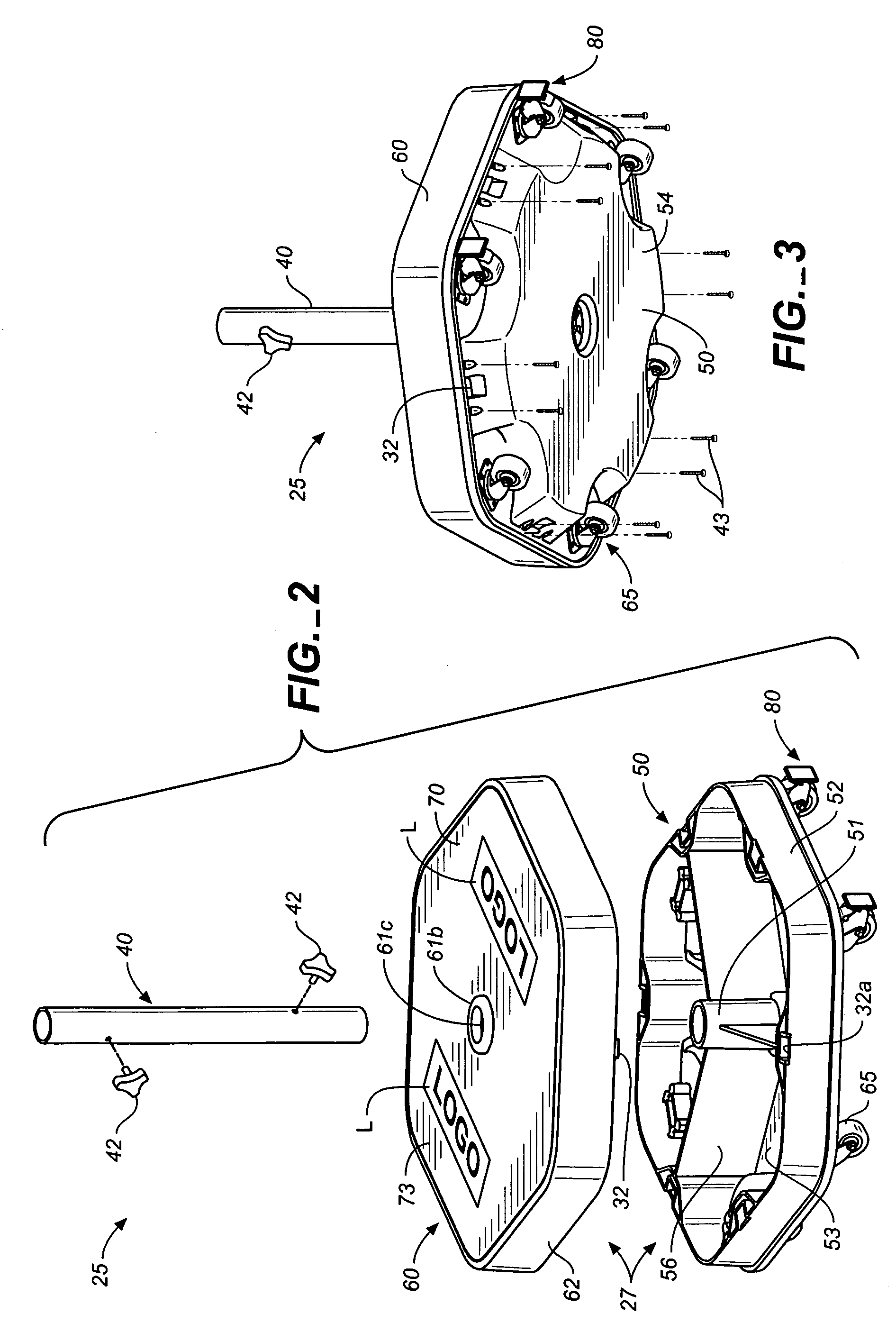
[0055]The present invention provides a novel umbrella base of the type used to hold the shaft of an umbrella such as a patio umbrella. In its various aspects the umbrella base of the invention provides mobility, can be stabilized once it reaches its predetermined location, has operative components that can be easily be removed and attached, such as for filling the base with a ballast material, and provides an easily viewed advertising display, including an interchangeable display. An umbrella base is also described that is adapted to contain a power source such as batteries and power feeds for users of the umbrella and an easily accessed power console.

[0056]Referring now to the drawings, FIGS. 1-11 show an embodiment of the invention and components thereof, wherein the umbrella base is a rolling umbrella base which is generally hexagonal in shape, which displays an advertising message, and which is capable of being locked in a set position after it has been moved. Base 25 is compris...


PUM


Abstract

An umbrella base is comprised of a body portion containing a power source for powering umbrella lights or electrical devices or appliances used around the umbrella or other furniture accessory held by the base. A power console is provided for use on or above the base to provide connectivity to the power supply.

Description

CROSS-REFERENCE TO RELATED APPLICATIONS[0001]This application claims the benefit of Provisional Application No. 60 / 533,737, filed Dec. 29, 2003.BACKGROUND OF THE INVENTION[0002]The present invention generally relates to the use of umbrellas, and in particular, to umbrella bases used to hold umbrellas in an upright position.[0003]Outdoor and patio umbrellas (collectively referred to as patio umbrellas) are widely used in personal, recreational and commercial settings. Typical commercial purchasers of patio umbrellas include hotels, resorts, restaurants, cafes, pubs and coffee houses. Because of their widespread use and the visual exposure they provide to users and passers-by, patio umbrella's have been popular as a media for corporate advertising. As more people spend time outside and become more educated about the harmful effect of the sun's direct rays, the demand for patio umbrella's is likely to increase along with the opportunity for providing advertising centered around the pat...

Claims


Application Information

Patent Timeline
Patent Type & Authority Patents(United States)
IPC IPC(8): A47B97/00A45B3/00A45B5/00E04H12/22G09F23/00
CPCG09F23/00E04H12/2246A45B2023/0012Y10S248/91
Inventor SMITH, JAMES C.TAYLOR, DAVID J.
Owner ROLLING UMBRELLAS INC
Why Eureka
Try Eureka