Method for automatic maximization of coverage in constrained stimulus driven simulation

a stimulus driven simulation and automatic maximization technology, applied in the field of test design, can solve the problems of inability to guarantee that such events will in fact occur during a limited duration, and achieve the effect of improving functional coverag

Active Publication Date: 2009-11-10
SYNOPSYS INC
View PDF13 Cites 23 Cited by
  • Summary
  • Abstract
  • Description
  • Claims
  • Application Information

AI Technical Summary

Benefits of technology

[0015]In some embodiments, the computer includes a coverage analyzer that uses test results to identify coverage goals that have not been met, i.e. unmet coverage goals. In these embodiments, the computer is further programmed to use the unmet coverage goals to prioritize coverage-based constraints that correspond to the unmet coverage goals at a higher priority for use in generating test vectors. Moreover, in some embodiments, coverage goals on non-input signals (e.g. goals on internal signals and / or output signals of the circuit) are also used with additional information from a human, hereinafter “correlations”, to automatically create and / or identify another type of coverage-based constraints (“non-input goal constraints”). A correlation indicates to the computer that a human-specified non-input signal tends to vary with one or more human-specified input signal(s). Use of the two different types of coverage-based constraints to generate test vectors provides flexibility in improving functional coverage to a level not obtained by use of any prior art known to inventors.

Problems solved by technology

However, there is no guarantee that such events will in fact occur during a limited duration within which simulation is performed, or that such events will occur even if the simulation duration is infinitely long.

Method used


Image

  • Method for automatic maximization of coverage in constrained stimulus driven simulation
  • Method for automatic maximization of coverage in constrained stimulus driven simulation
  • Method for automatic maximization of coverage in constrained stimulus driven simulation

Examples


Embodiment Construction

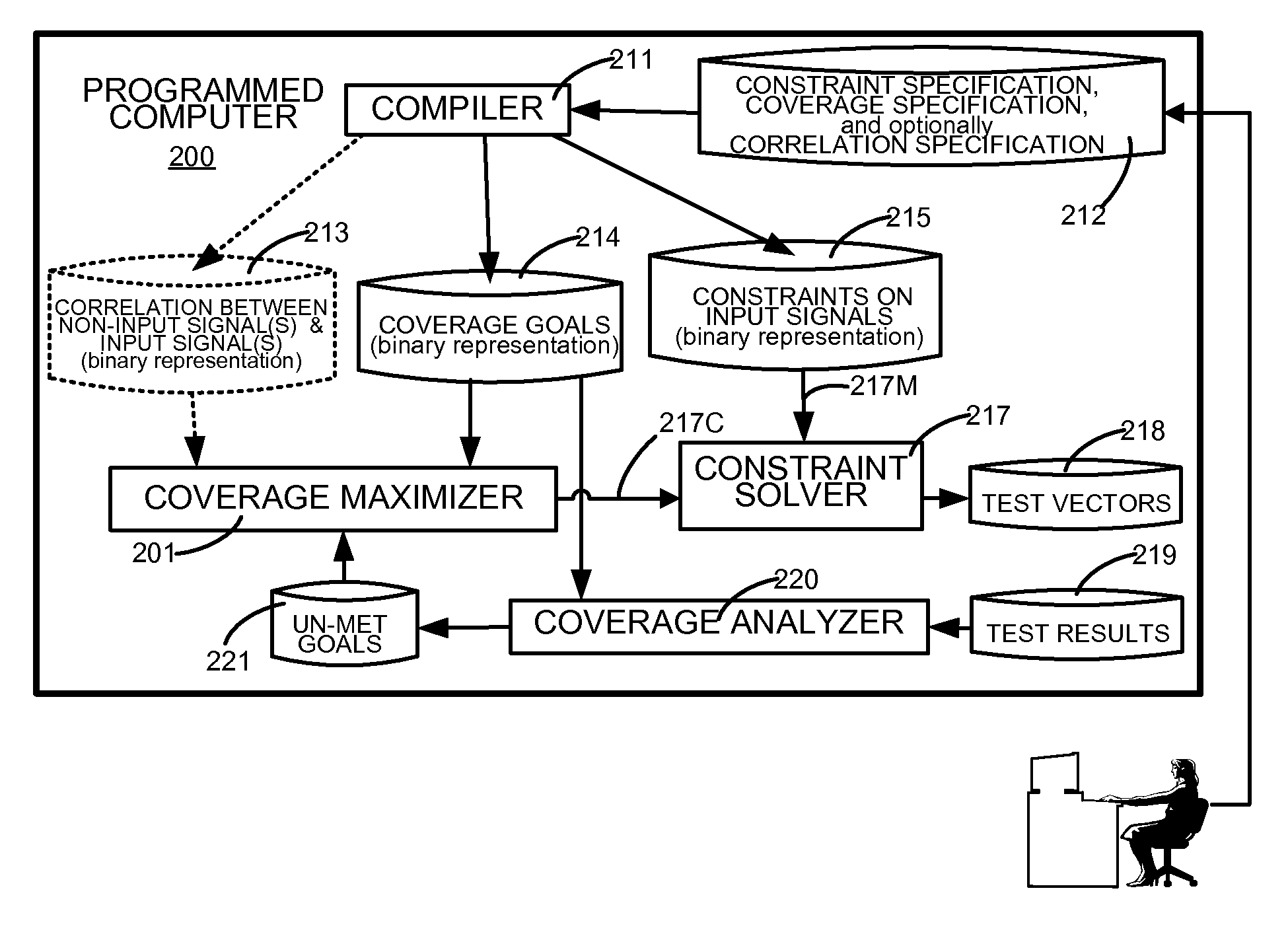
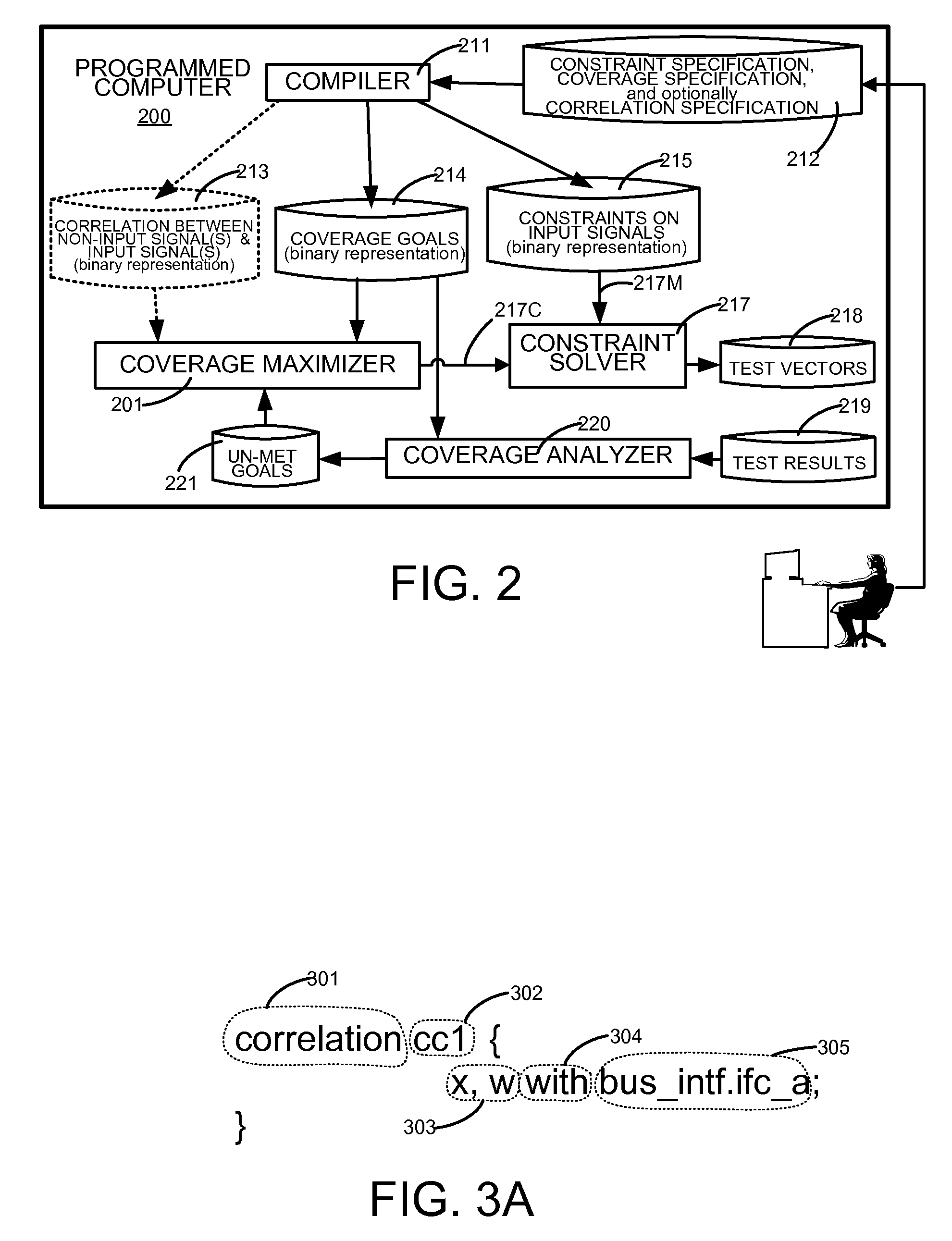
[0027]A computer 200 (FIG. 2) is programmed with software (“compiler”) to read text files which specify constraints on input signals of an integrated circuit (IC) design in a constraints specification file, and coverage goals for the input signals in a coverage specification file. The two files are typically held in a non-volatile memory 212 of computer 200, and both files are normally expressed in a Hardware Verification Language (HVL), such as OpenVera or System Verilog.

[0028]Hence, compiler 211 (FIG. 2) that is included in computer 200 can be any OpenVera compiler of the type available from Synopsys, Inc. of Mountain View, Calif., or alternatively any System Verilog compiler that may be available in the industry, such as Questa compiler available from Mentor Graphics. Note that a compiler of the type commonly available in the industry is customized in various embodiments to maintain specific associations inside computer 200 between constrained signals and covered signals as descr...


PUM


Abstract

A computer increases coverage in simulation of a design of a circuit by processing goals for coverage differently depending on whether or not the goals are on input signals of the circuit. Specifically, goals on input signals are used to automatically formulate constraints (“directly-derived constraints”) on values of input signals in test vectors. Goals on non-input signals (e.g. internal / output signals) are used with correlations to automatically formulate more additional constraints (“correlation-derived constraints”), by use of goals on non-input signals. The correlations indicate which non-input signals are associated with which input signals. The correlations are received from, for example, a human designer of the circuit. Depending on the embodiment, one or more of the automatically derived constraints are used with human-supplied constraints, to generate test vectors e.g. using a constraints solver, such as a satisfiability (SAT) engine. The test vectors are supplied to a simulator for functional verification.

Description

CROSS REFERENCE TO RELATED APPLICATION[0001]This application is related to and incorporates by reference herein in its entirety US patent application 11 / 831,745 entitled “METHOD FOR AUTOMATICALLY EXTRACTING A FUNCTIONAL COVERAGE MODEL FROM A CONSTRAINT SPECIFICATION” that is commonly owned and filed on Jul. 31, 2007.BACKGROUND[0002]1. Field of the Invention[0003]The invention relates to design of tests that are used in simulation of design(s) of circuits. More specifically, the invention relates to a method and an apparatus for automatically increasing functional coverage in stimulus driven simulation of the circuit designs that are typically implemented in integrated circuit (IC) chips.[0004]2. Related Art[0005]In the design of integrated circuit (IC) chips, it is common to test IC designs by use of a testbench. A test bench in a high-level verification language (HVL) environment includes test generators that randomly generate input signals for the IC design. U.S. Pat. No. 6,141,63...

Claims


Application Information

Patent Timeline
Patent Type & Authority Patents(United States)
IPC IPC(8): G06F17/50G06F11/00G01R31/28G06F9/45
CPCG06F17/5081G01R31/31835G06F30/398
Inventor THAKUR, SHASHIDHAR ANILDANI, RAHUL HARI
Owner SYNOPSYS INC
Why Eureka
Try Eureka