Injector fuel filter with built-in orifice for flow restriction

a fuel filter and injector technology, applied in the direction of water mains, service pipes, machines/engines, etc., can solve the problems of adding cost and complexity to the fuel system, erratic fuel delivery to the cylinder, etc., to reduce or eliminate the pressure pulsation through the fuel injector. , to reduce the pressure pulsation in the fuel lin

Active Publication Date: 2009-11-17
DELPHI TECH IP LTD
View PDF92 Cites 43 Cited by
  • Summary
  • Abstract
  • Description
  • Claims
  • Application Information

AI Technical Summary

Benefits of technology

[0007]The present invention addresses the above need by providing a design and method for reducing pressure pulsations in a fuel line caused by the opening and closing of the fuel injectors. In a preferred embodiment, a restriction orifice is provided in the fuel injector filter of a respective fuel injector. The restriction orifice acts to break up and thus reduce or eliminate pressure pulsations through the fuel injector.

Problems solved by technology

In such injector-based systems, these pulses cause high frequency pressure waves of significant amplitude to propagate through the fuel rail(s) potentially causing erratic delivery of fuel to the cylinders.
While this method is effective at reducing pressure pulsations, it also adds cost and complexity to the fuel system.

Method used


Image

  • Injector fuel filter with built-in orifice for flow restriction
  • Injector fuel filter with built-in orifice for flow restriction

Examples


Embodiment Construction

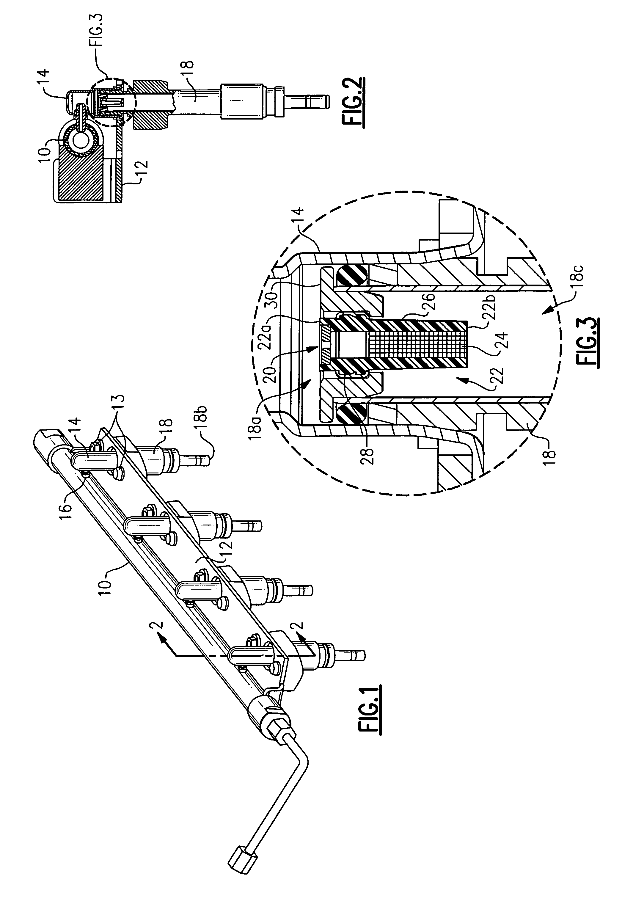
[0012]Referring to FIG. 1, there is seen a fuel rail 10 for mounting to an engine (not shown) via bracket 12. The fuel rail 10 is laterally offset from the injector sockets 14 to provide access to the bolts 13 which pass through openings in bracket 12. With the fuel rail 10 laterally offset from the injector sockets 14, jump tubes 16 are required to provide a fluid path from the rail 10 to a respective injector socket 14. Injector sockets 14 are known in the art and provide a coupling between a respective fuel injector 18 and the fuel rail 10.

[0013]It is noted that fuel rail 10 and bracket 12 are shown for purposes of environment only, and the present invention may be used in any fuel delivery system having one or more fuel injectors.

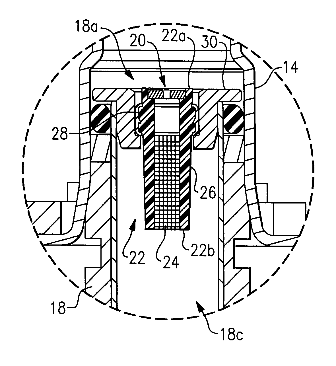
[0014]Fuel injectors 18 each have a fuel inlet end 18a and fuel outlet end 18b. Fuel is thus directed through fuel outlet end 18b upon the opening of the injector. As stated above, fuel injectors open and close very rapidly in order to provide the corre...


PUM

PropertyMeasurementUnit
diameteraaaaaaaaaa
diameteraaaaaaaaaa
pressureaaaaaaaaaa

Abstract

Apparatus and method for substantially reducing or eliminating pressure pulsations caused by the opening and closing of fuel injectors. A preferred embodiment provides a restriction orifice adjacent the inlet end of a fuel injector filter of a respective fuel injector.

Description

TECHNICAL FIELD[0001]The present invention relates to fuel injectors for internal combustion engines; more particularly, to a fuel injector with a built-in orifice for reducing pressure pulsations.BACKGROUND OF THE INVENTION[0002]Fuel injectors for controllably metering fuel to the combustion cylinders of internal combustion engines are well known. For ease and reliability in manufacturing, the fuel injectors typically are mounted by their inlet ends at appropriate intervals into a rigid fuel supply line harness, appropriately configured to place the injection end of each fuel injector into its corresponding injection socket in the manifold runner. Such a harness is known as a fuel injector rail, or simply a fuel rail.[0003]In a typical direct injector fuel injection system, each injector is programmed to pulse or open every other revolution of the engine crankshaft. During an injector opening event in a direct injector fuel injection system, the measured fuel pressure in the fuel r...

Claims


Application Information

Patent Timeline
Patent Type & Authority Patents(United States)
IPC IPC(8): B01D35/02B01D21/28F02D1/06
CPCF02M61/165F02M61/14F02M2200/315Y10S239/23Y10T137/794
Inventor WELLS, ALLAN R.KEEGAN, KEVIN R.
Owner DELPHI TECH IP LTD
Why Eureka
Try Eureka