
Cathode element for use in an electrolytic cell intended for production of aluminum

a cathode element and electrolytic cell technology, applied in the direction of cells, isotope separation, electrolyte, etc., can solve the problems of limiting the life of the pot, affecting the efficiency of the cathode, so as to achieve a large drop in the global cathode voltage and a strong reduction of the current density

Active Publication Date: 2009-11-17
ALUMINUM PECHINEY
View PDF16 Cites 3 Cited by
  • Summary
  • Abstract
  • Description
  • Claims
  • Application Information

AI Technical Summary

Benefits of technology

"The present invention is about a system that reduces the voltage drop in the cathode of electrolytic cells to save energy. The invention includes a cathode element with a carbon block and a steel connection bar. The connection bar has a metal insert inside it to improve electrical conductivity. The use of the metal insert results in a significant reduction in voltage drop and current density at the head of the block. The invention also includes an electrolytic cell comprising the cathode element."

Problems solved by technology

Furthermore, changes to the properties of cathode blocks have led to the emergence of new problems such as, for example, erosion of cathodes.
For example, it has been observed that as the quantity of graphite contained in cathode blocks increases, a block becomes more sensitive to erosion problems at the head of the block.
These very high erosion areas can limit the life of the pot, which is a major economic problem for an aluminum reduction plant.
However, these solutions are, first of all, expensive because copper is more expensive than steel and the copper quantities involved may be high.
Therefore the extra cost associated with the presence of copper components increases very quickly.
Furthermore, even the known revised configurations are not fully satisfactory.
These configurations cause reductions in the global cathode voltage drop (in other words including the voltage drop in the bar) on the order of 50 mV, which is too low to justify the additional investment costs, and produce relatively high peak current densities at the head of the block, namely more than about 12 kA / m2.

Method used


Image

  • Cathode element for use in an electrolytic cell intended for production of aluminum
  • Cathode element for use in an electrolytic cell intended for production of aluminum
  • Cathode element for use in an electrolytic cell intended for production of aluminum

Examples


Embodiment Construction

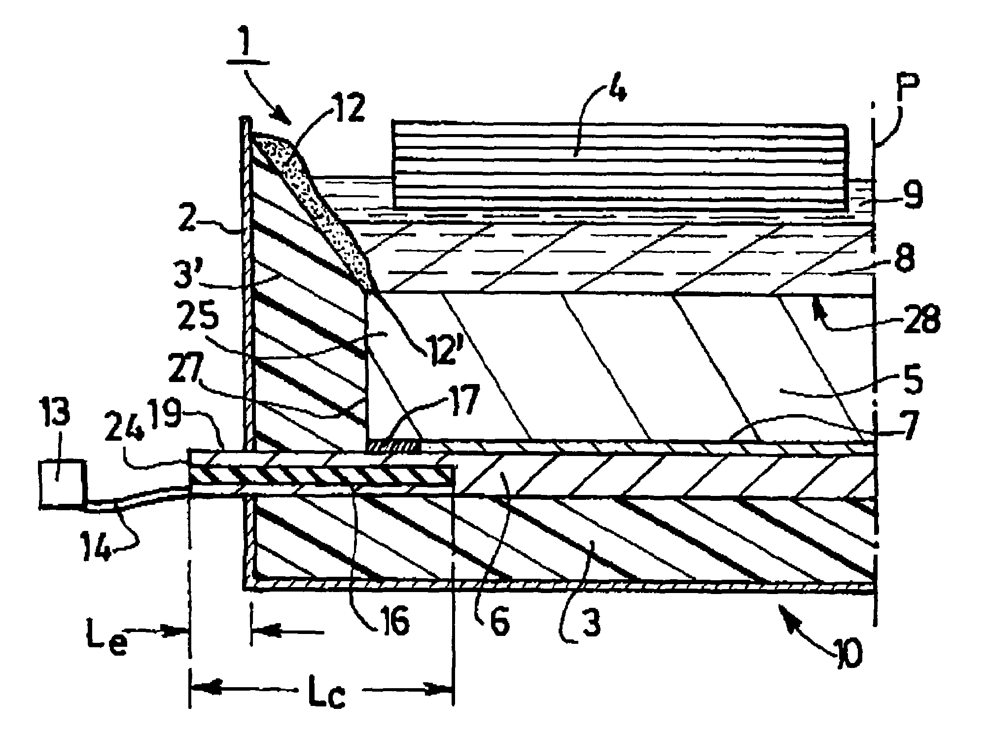
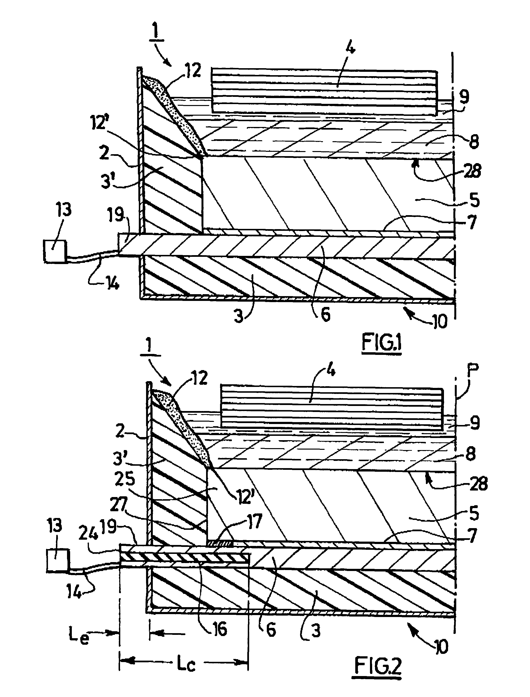
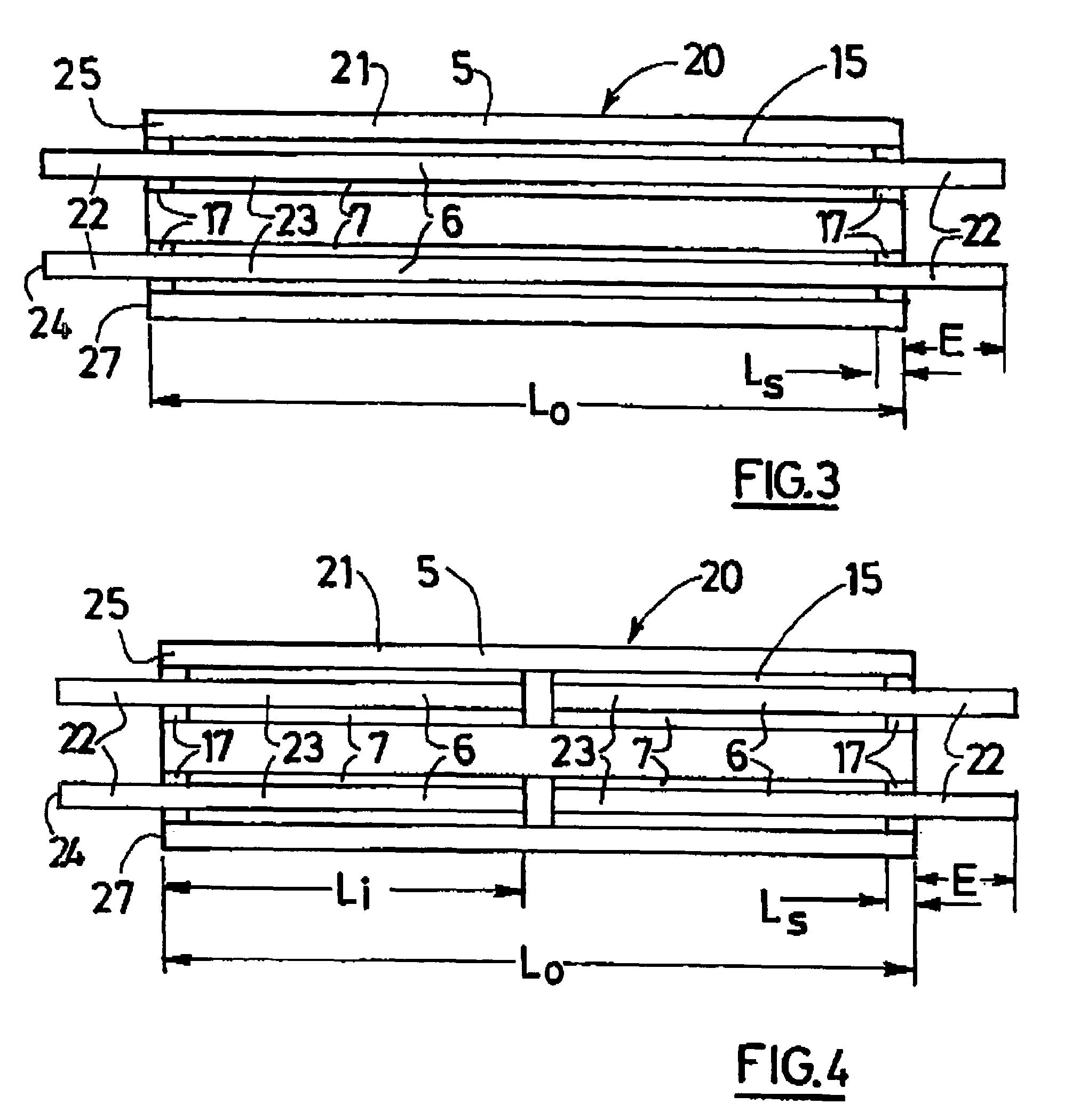
[0036]It was discovered by the present applicants that a large part of the drop in the cathode voltage (about one third) is located in the part of the bar “outside the block” (i.e. that part that extends out of the block). In fact, the current density in the bar increases towards the part of the bar located outside the block and reaches a maximum value at the point the bar exits the block. Consequently, over the entire part of the bar located “outside the block”, a small section carries a large quantity of current, which causes a large voltage drop.

[0037]The applicants had the idea of combining an unsealed zone close to the head of the cathode block, and at least one insert in each external segment of the connection bar that extends preferably over substantially the entire length of the segment. They observed that, unexpectedly, the combined effect of these characteristics very significantly reduces the peak current density that exists at the head of the block, (in other words close...


PUM

PropertyMeasurementUnit
distanceaaaaaaaaaa
peak current densitiesaaaaaaaaaa
heightaaaaaaaaaa

Abstract

This invention relates to a cathode element for use in a pot of an electrolytic cell intended for production of aluminum. The cathode element comprises a cathode block and a steel connection bar. The connection bar includes at least one metal insert, whose electrical conductivity is greater than the electrical conductivity of the said steel. The presence of an insert according to the invention can simultaneously result in a very large drop in the global cathode voltage and a very strong reduction in the current density at the head of the block.

Description

CROSS REFERENCE TO RELATED APPLICATIONS[0001]This application claims priority under 35 USC 119 from FR 0403497 filed Apr. 2, 2004, the content of which is incorporated herein by reference in its entirety.BACKGROUND OF THE INVENTION[0002]1. Field of the Invention[0003]The present invention relates generally to the production of aluminum by fused bath electrolysis. In particular, it relates to cathode elements suitable for use in electrolytic cells intended for production of aluminum.[0004]2. Description of Related Art[0005]The cost of energy is an important concern when analyzing the operating costs of aluminum reduction plants. Consequently, a reduction in the specific energy consumption of electrolytic cells is very important for these plants. The specific consumption of a cell is equal to the energy consumed by the cell to produce one metric ton (tonne) of aluminum. It is expressed in kWh / t and, for a constant current efficiency, is directly proportional to the electrical voltage ...

Claims


Application Information

Patent Timeline
Patent Type & Authority Patents(United States)
IPC IPC(8): C25C3/08C25C3/16
CPCC25C3/16C25C3/08
Inventor BONNAFOUS, DELPHINEBASQUIN, JEAN-LUCVANVOREN, CLAUDE
Owner ALUMINUM PECHINEY
Learn More