Asynchronous sample rate conversion using a digital simulation of an analog filter

a digital simulation and sample rate technology, applied in the field of processing digital signals, can solve the problems of large amount of memory needed to store, difficult type of conversion, and inability to attract many applications, and achieve the effect of less memory

Active Publication Date: 2009-11-17
DOLBY LAB LICENSING CORP
View PDF1 Cites 13 Cited by
  • Summary
  • Abstract
  • Description
  • Claims
  • Application Information

AI Technical Summary

Benefits of technology

[0013]It is an object of the present invention to provide high-quality sample rate conversion that can adapt to changes in source and destination sample rates and that requires much less memory than conventional techniques.
[0014]According to the present invention, sample-rate conversion may be implemented using a discrete-time digital simulation of a continuous-time analog filter. This approach allows sample-rate conversion filters to be implemented with a very high time resolution without need for large amounts of memory to store tables of coefficients.

Problems solved by technology

Unfortunately, many of these components require signals that have different sample rates.
This type of conversion is often difficult to implement because the cutoff frequency of the low-pass filter is linked to the source sample rate when the sample rate is converted upwards but is linked to the destination sample rate when the sample rate is converted downwards.
In addition to the difficulties explained above, the FIR implementation is not attractive in many applications because it requires a large amount of memory to store filter coefficients.
A large amount of memory is needed to store all of these coefficients.
Alternatively, interpolation can be used with a smaller number of coefficient sets but much memory is still required because FIR filter coefficients generally cannot be determined accurately by interpolation between two sets of coefficients that represent widely-spaced events.

Method used


Image

  • Asynchronous sample rate conversion using a digital simulation of an analog filter
  • Asynchronous sample rate conversion using a digital simulation of an analog filter
  • Asynchronous sample rate conversion using a digital simulation of an analog filter

Examples


Embodiment Construction

A. Introduction

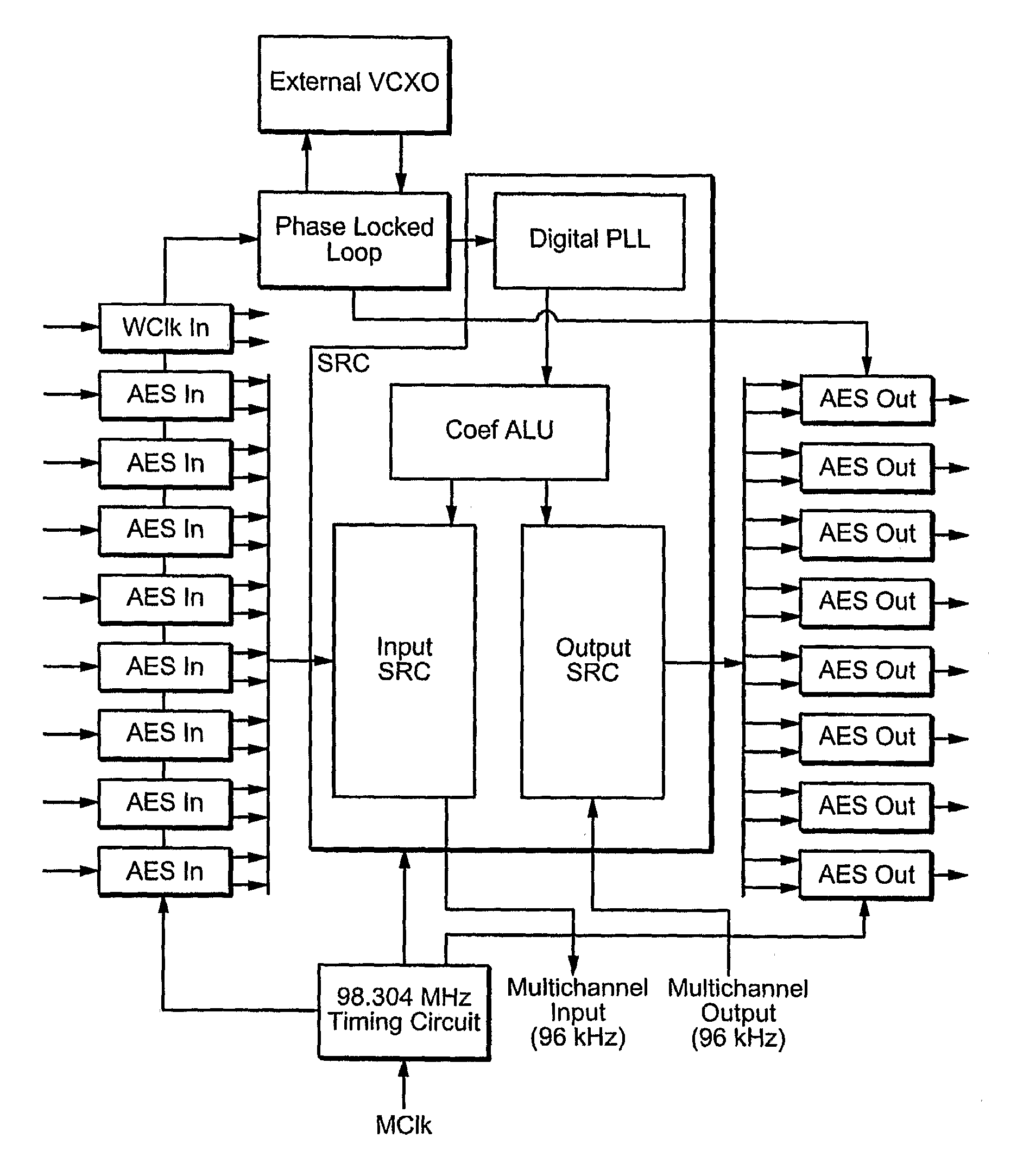
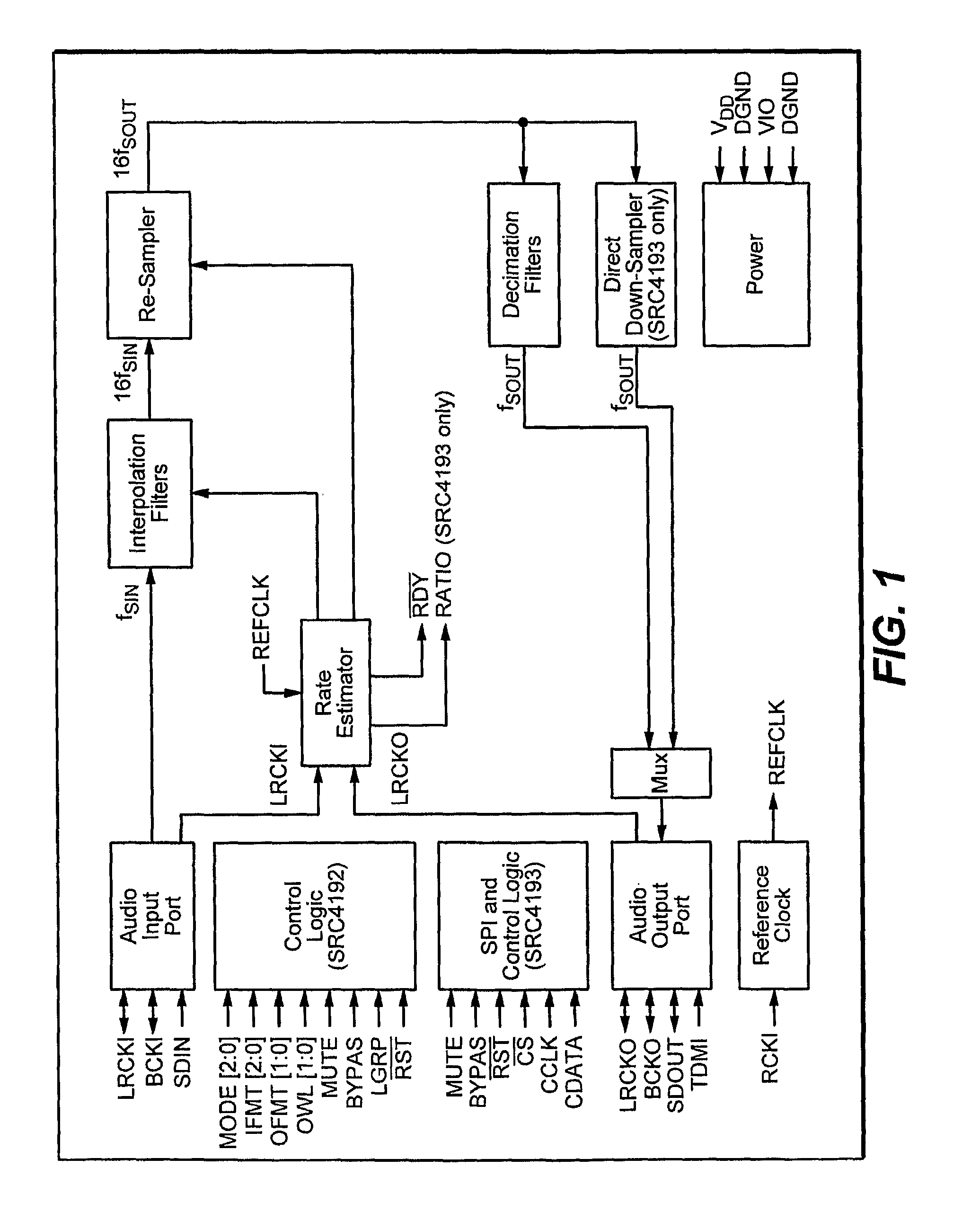
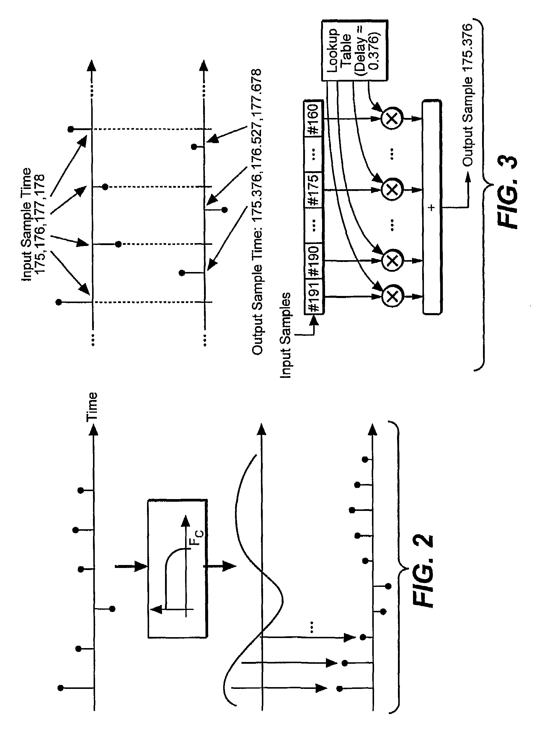
[0025]FIG. 1 is a schematic block diagram of the SRC4193 chip mentioned above that performs sample-rate conversion according to a conventional sample-rate conversion technique. This technique, which is illustrated schematically in FIG. 2, uses finite impulse response (FIR) filters to interpolate and decimate digital signals by various ratios to obtain the desired destination sample rate. The sample-rate converter shown in FIG. 1 uses one low-pass filter to interpolate the source signal samples up to an intermediate rate that is sixteen times higher than the source sample rate. Another low-pass filter decimates the intermediate samples down to the destination sample rate. Under certain conditions, the decimation filter can be bypassed and the intermediate samples down-sampled directly to the desired destination sample rate.

[0026]Referring to the example shown in FIG. 3, a conventional sample-rate converter computes a destination signal sample for time t=175.376 by coll...


PUM


Abstract

The sample rate of a digital signal is converted by a digital simulation of an analog filter. The simulation can update the states of complex poles in the analog filter at arbitrary times using different techniques. One technique updates the states at variable rates. Other techniques update the states at a fixed rate in response to values of input or output samples that are modified to account for offsets between the times of the samples and the times the states are updated. The states may be updated by using interpolations of complex exponential functions. Values of the complex exponential functions may be obtained from a product of values obtained from multiple lookup tables.

Description

TECHNICAL FIELD[0001]The present invention pertains generally to processing digital signals and pertains more specifically to converting the sample rate of a digital signal.BACKGROUND ART[0002]An increasing number of devices including professional and consumer video and audio devices contain circuitry that processes digital signals. The signals that need to be passed between components of these types of systems are often digital rather than analog. Unfortunately, many of these components require signals that have different sample rates. Differences in sample rate can occur even between devices that use the same nominal rate if those devices operate with digital clocks or oscillators that differ in frequency. These differences may vary over time.[0003]In situations where the output signal of one device is intended to be the input signal of another device, it is often necessary to convert the sample rate of the signal so that the two devices can work together. For ease of discussion i...

Claims


Application Information

Patent Timeline
Patent Type & Authority Patents(United States)
IPC IPC(8): H03M7/00
CPCH03H17/0422
Inventor MCGRATH, DAVID STANLEY
Owner DOLBY LAB LICENSING CORP
Why Eureka
Try Eureka