
Detector array and system

a technology of detector arrays and arrays, applied in the field of detector arrays for imaging technology, can solve problems such as reducing repeatability, reducing measurement or imaging repeatability, and instability of machine-to-machine data

Inactive Publication Date: 2009-11-17
GENERAL ELECTRIC CO
View PDF3 Cites 9 Cited by
  • Summary
  • Abstract
  • Description
  • Claims
  • Application Information

AI Technical Summary

Benefits of technology

This configuration significantly reduces crosstalk-induced artifacts, enhancing image quality by improving linearity, sensitivity, and dynamic range, while relaxing alignment precision requirements and reducing image noise.

Problems solved by technology

Mechanisms which degrade the signals from the diode array can cause machine-to-machine data instability, or reduce measurement or imaging repeatability, and may give rise to data distortion causing imaging defects such as ring artifacts, bands or smudges in the resultant data, when it is employed to form a visible image, or engender inaccuracy and / or reduced repeatability in the context of automated characterization of tissues.
Signal artifacts resulting from the photodetector array itself also may pose some fundamental limits on overall system performance.
Additionally, achieving alignment of the scintillator cell array with the photodiode array presents difficulty in manufacturing, with unwanted signal characteristics or artifacts being associated with residual imprecision in that process.

Method used


Image

  • Detector array and system
  • Detector array and system
  • Detector array and system

Examples


Embodiment Construction

[0023]In the following detailed description, reference is made to the accompanying drawings that form a part hereof, and in which are shown, by way of illustration, specific embodiments that may be practiced. These embodiments are described in sufficient detail to enable those skilled in the art to practice the embodiments, and it is to be understood that other embodiments may be utilized, and that logical, mechanical, electrical and other changes may be made, without departing from the scope of the embodiments.

[0024]Ranges of parameter values described herein are understood to include all subranges falling therewithin. The following detailed description is, therefore, not to be taken in a limiting sense.

[0025]The detailed description is divided into four sections. In the first section, a system level overview is provided. In the second section, an example of a pixelated photodiode array is described. In the third section, embodiments of improvements in tiled detector assemblies are...


PUM


Abstract

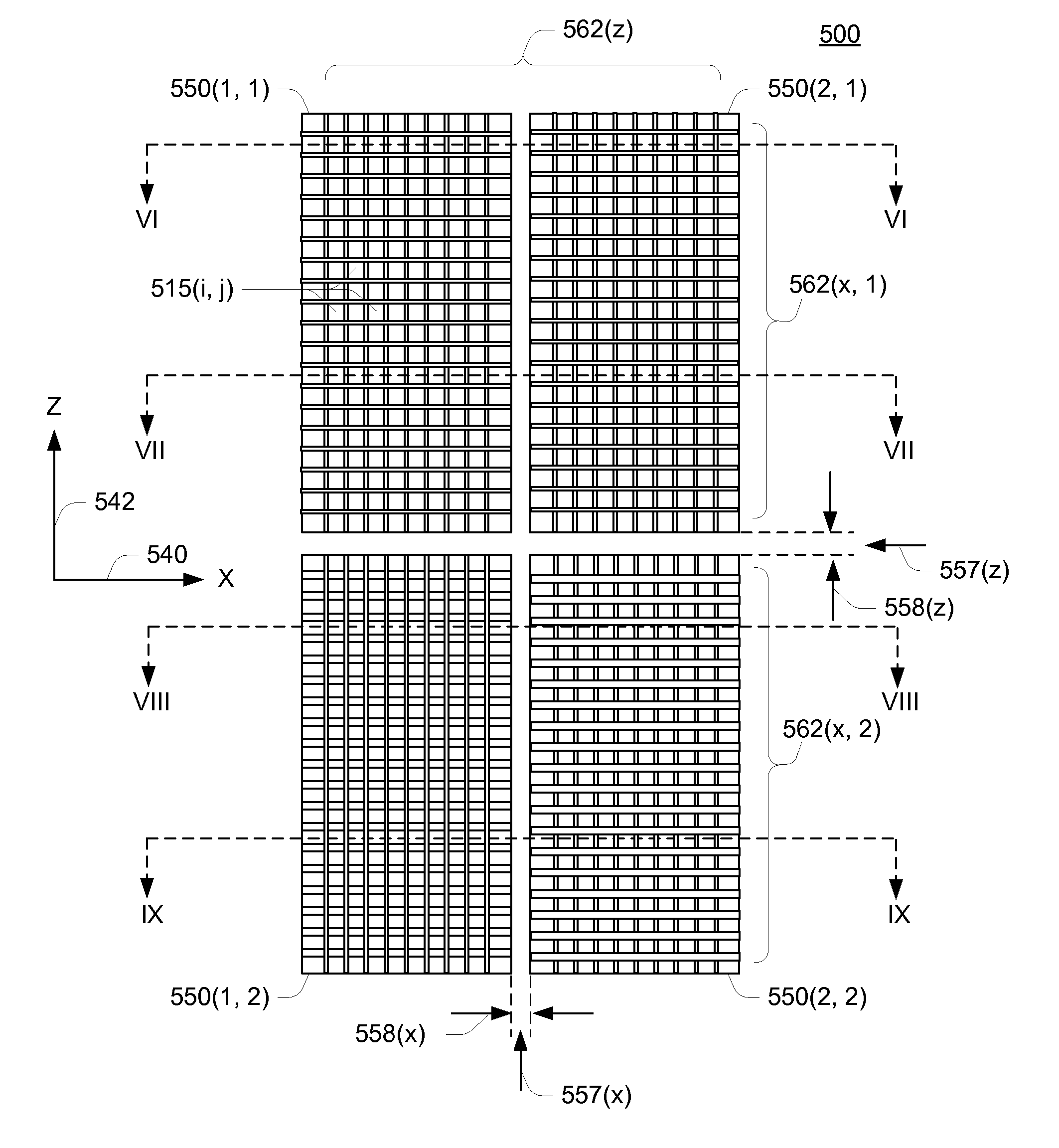
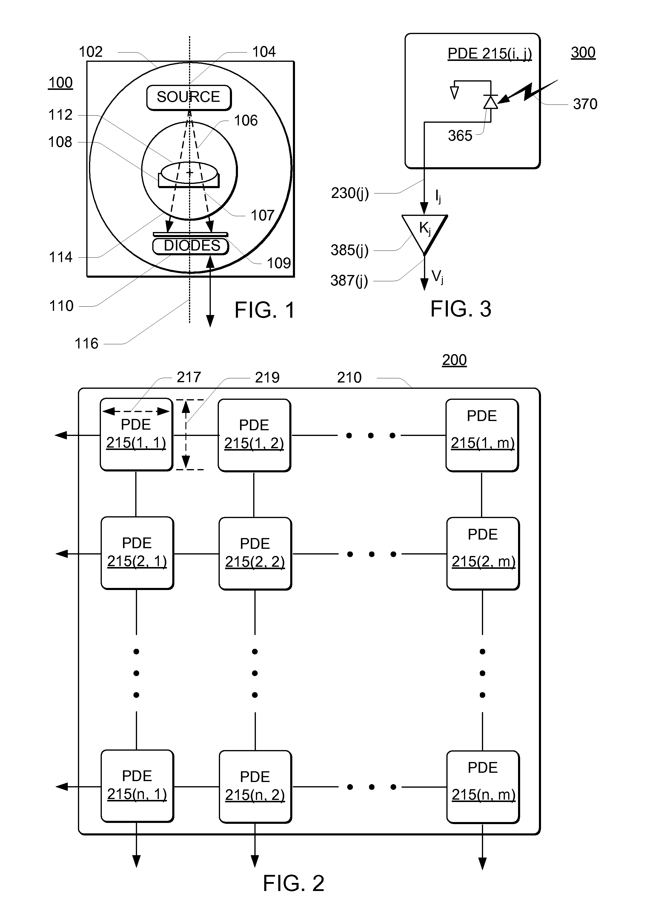
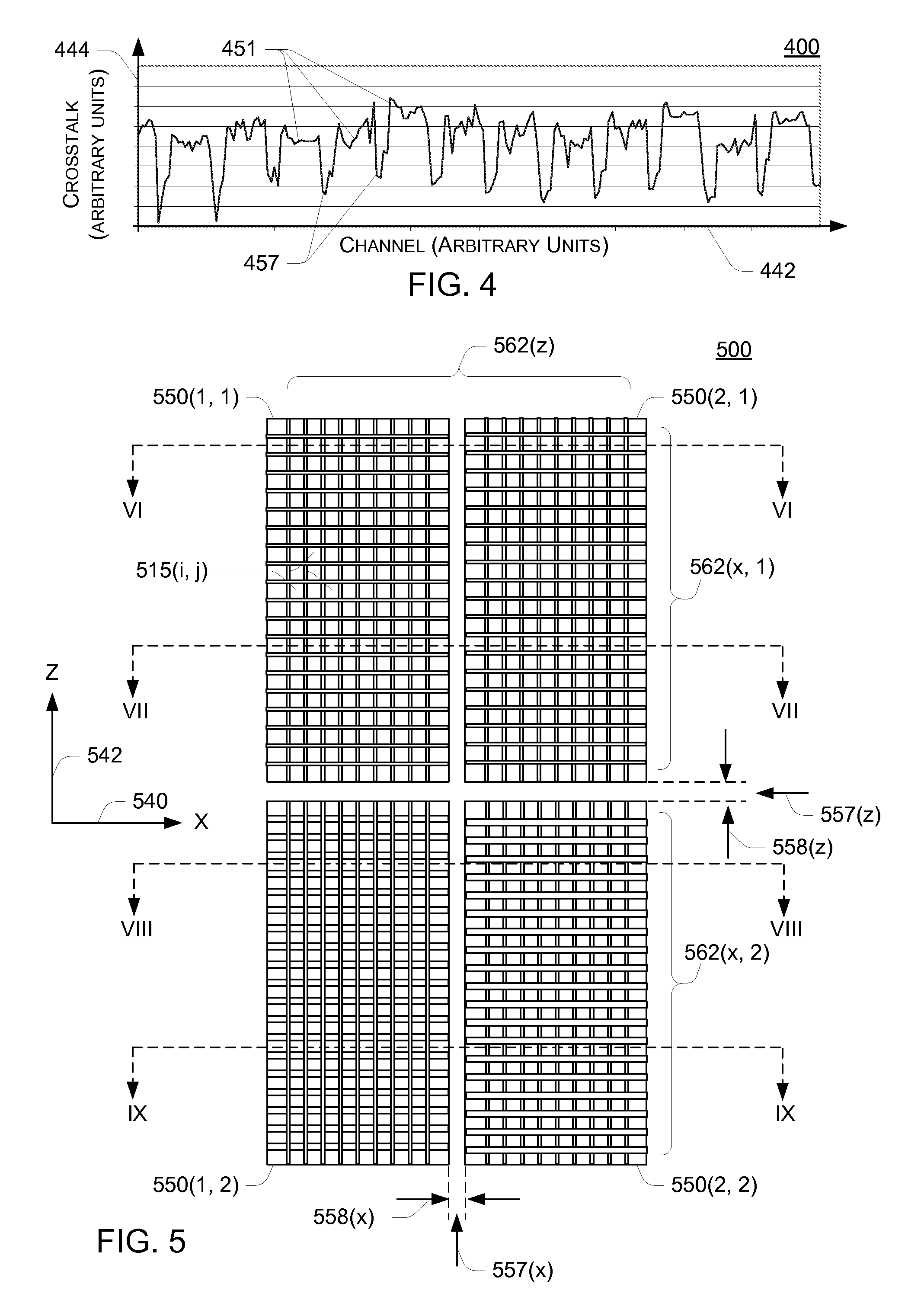
In some embodiments, an optical mask for a CT detector is disclosed. In some embodiments, the mask is intercalated between a photodiode array and a scintillator array forming the CT detector. In some embodiments, the optical mask may extend along one or more axes and differentially absorbs and / or reflects light emitted from the scintillators at edges of photodiodes forming the diode array, with less absorption or reflection at edges of tiled die forming the diode array than in central portions of each of the die. Through selective absorption and / or reflection, transference of light photons from a scintillator to the photodiode corresponding to a neighboring scintillator is spatially modified, at least partially compensating for spatial differences in crosstalk signals between adjacent pairs of photodiode / scintillator cell elements. This reduction in differential crosstalk reduces artifacts in a reconstructing data descriptive of internal portions of a subject, which improves diagnostic value of the data.

Description

FIELD OF THE DISCLOSURE[0001]This disclosure relates generally to detector arrays for imaging technology, and in particular to a detector array providing improved signal detection capabilities and a computed tomography (CT) X-ray system incorporating the detector array.BACKGROUND[0002]Many medical diagnostic, surgical and interventional procedures rely on imaging tools to provide information descriptive of status of visually perceived representations of portions or organs of a patient. In part as a result of increasing sophistication of medical tools in general, and imaging apparatus in particular, more types of imaging devices are being adapted for application in the context of medical diagnostics and procedures.[0003]In many instances, medical tools capable of rendering images of organs or tissues have found great utility and have been adapted to facilitate a broad variety of medical needs. These applications have resulted in development of a gamut of specialized imaging tools, in...

Claims


Application Information

Patent Timeline
Patent Type & Authority Patents(United States)
IPC IPC(8): A61B6/00
CPCH04N5/32G01T1/2985H04N23/30
Inventor IKHLEF, ABDELAZIZSAEED, FAISAL
Owner GENERAL ELECTRIC CO
Learn More