
In-wheel motor system and method of installing the same

a technology of in-wheel motors and motor components, which is applied in the direction of electric propulsion mounting, electric devices, transportation and packaging, etc., can solve the problems of large changes in the ground load of tires, and deteriorating road holding properties, so as to achieve less assembly accuracy

Inactive Publication Date: 2009-11-24
BRIDGESTONE CORP
View PDF7 Cites 9 Cited by
  • Summary
  • Abstract
  • Description
  • Claims
  • Application Information

AI Technical Summary

Benefits of technology

The present invention provides an in-wheel motor system with a disk-like plate that can be easily mounted to a wheel and turn smoothly with the direct drive motor module. The system includes a wheel with holes in it, guide holes at positions corresponding to the holes, and connection pins that fit into the guide holes and holes on the wheel. The pins have mating portions that fit with the guide holes, and the wheel can be easily mounted even if the assembly accuracy is not very high. The invention also provides methods for installing the system and supporting the motor module to the wheel. The technical effects of the invention include improved mounting reliability and smoother wheel rotation.

Problems solved by technology

It is generally known that, in a vehicle having a suspension mechanism such as a spring around a wheel, as the mass of parts under the spring such as a wheel, knuckle and suspension arm, so-called “unsprung mass” increases, changes in the ground load of a tire when running on an uneven road become larger, thereby deteriorating road holding properties.
However, in a conventional in-wheel motor which is fixed to a spindle shaft connected to a part such as an upright or knuckle which is one of parts around a wheel of the vehicle so that a motor rotor and a wheel can turn, the above unsprung mass increases by the weight of the in-wheel motor, whereby changes in the ground load of the tire become large, thereby deteriorating road holding properties (refer to patent documents 1 to 3, for example).

Method used


Image

  • In-wheel motor system and method of installing the same
  • In-wheel motor system and method of installing the same
  • In-wheel motor system and method of installing the same

Examples


Embodiment Construction

[0041]Preferred embodiments of the present invention will be described hereinunder with reference to the accompanying drawings.

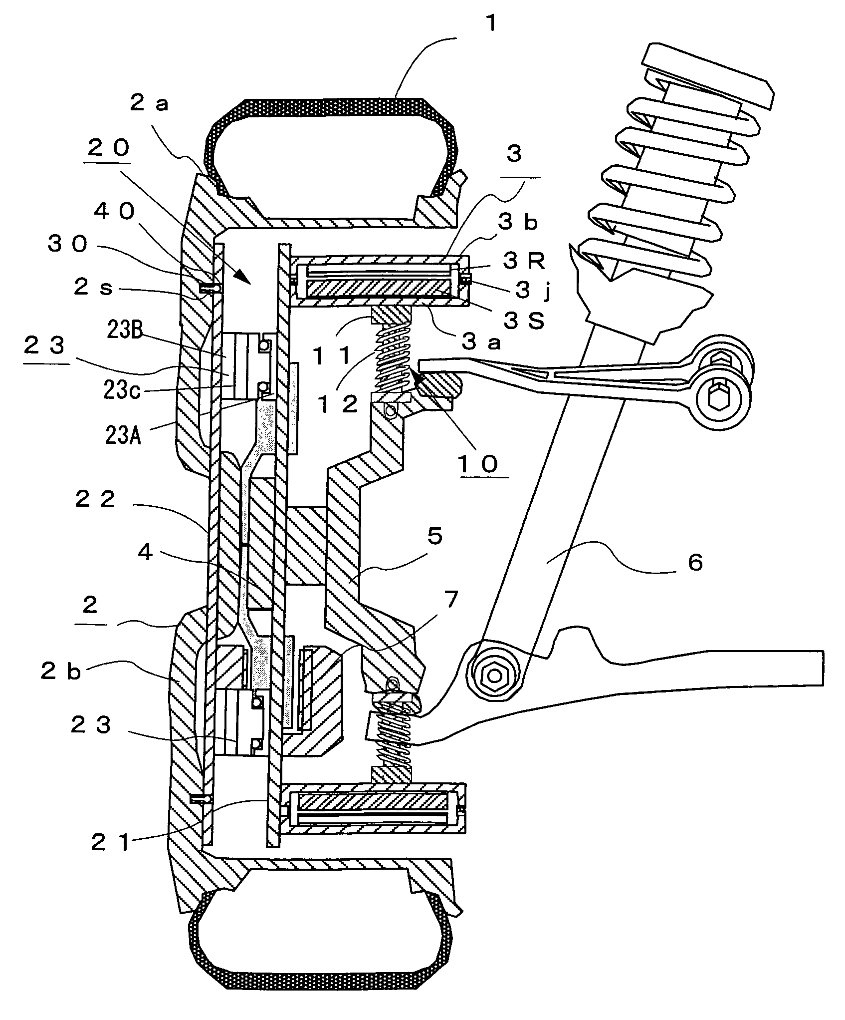
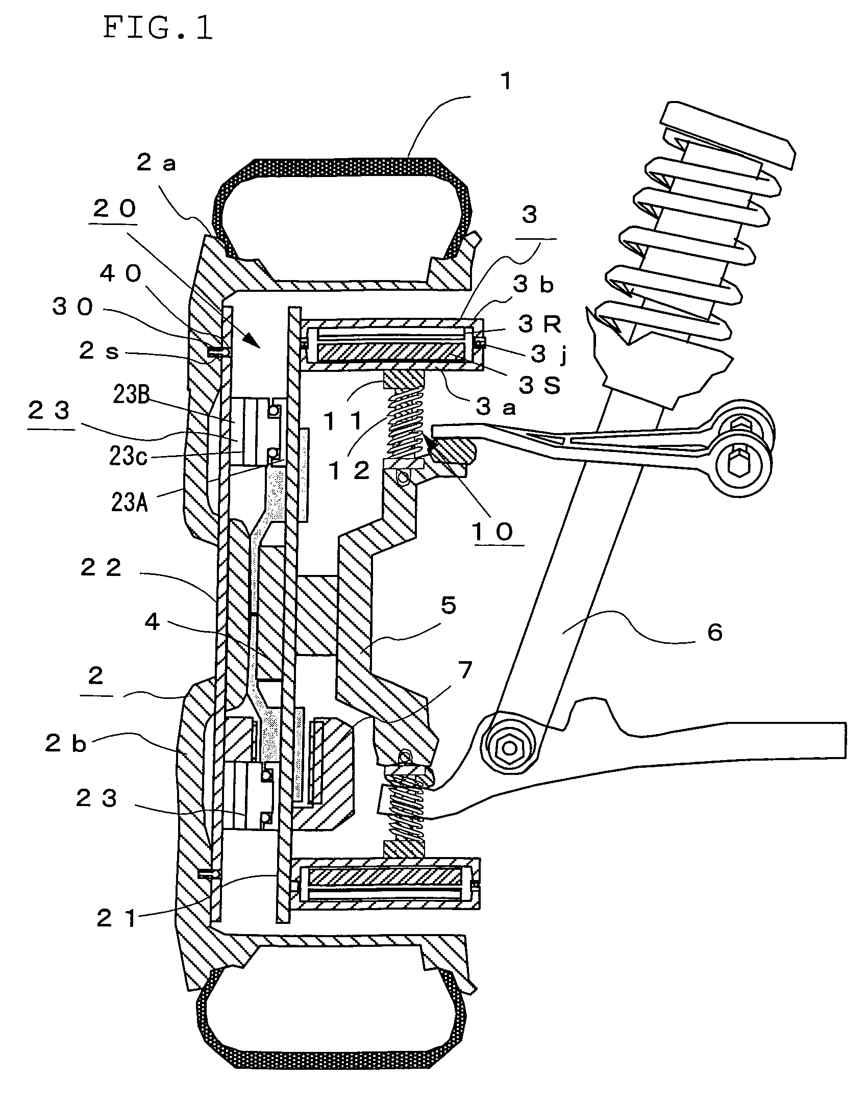
[0042]FIG. 1 is a longitudinal sectional view of an in-wheel motor system according to a preferred embodiment of the present invention. In FIG. 1, reference numeral 1 denotes a tire, 2 a wheel consisting of a rim 2a and a wheel disk 2b, 3 an outer rotor type in-wheel motor which comprises a stator 3S fixed to a non-rotating side case 3a arranged on the inner side in the radial direction and a rotor 3R fixed to a rotating side case 3b rotatably connected to the above non-rotating side case 3a through a bearing 3j and arranged on the outer side in the radial direction, 4 a hub connected to the wheel 2 at its rotary shaft, 5 a knuckle connected to the above hub 4 by an unshown bearing, 6 a suspension member composed of a shock absorber, 7 a brake unit composed of a brake disk mounted to the above hub 4, and 10 a buffer mechanism comprising a direct-acting guide...


PUM


Abstract

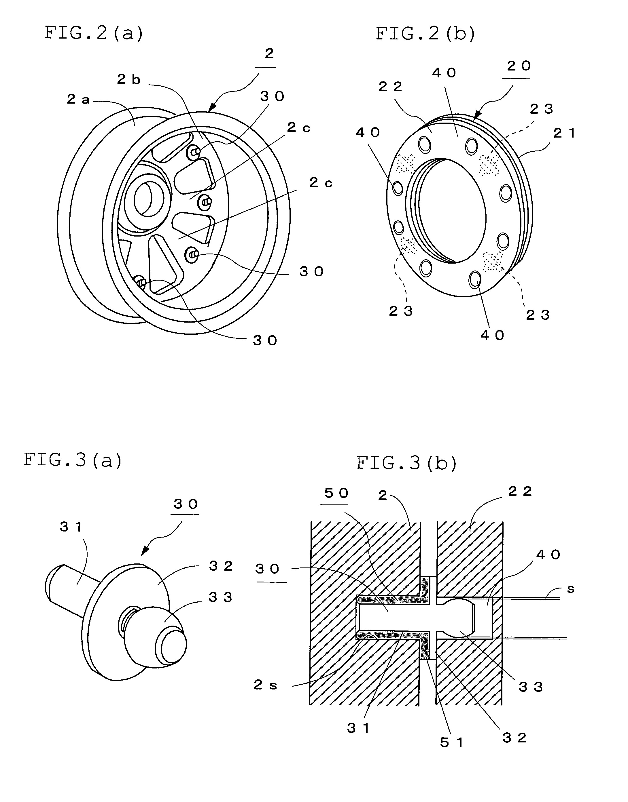
A direct drive motor module has hollow disk-like plates (21, 22) for interconnecting the rotation side of an in-wheel motor (3) and a wheel (2) and a drive force transmission mechanism (20) comprising cross guides (23) for guiding the plates (21, 22) in the vertical direction. To mount the direct drive motor module to the wheel (2), attachment holes (2s) are formed in the spoke portions of the wheel (2), the fixing portions of connection pins (30) having a spherical pin head which is a mating portion are fitted in the attachment holes (2s), guide holes (40) having a predetermined clearance relative to the outer diameter of the pin head (33) are formed in the wheel side plate (22) supporting the wheel (2) sides of the cross guides (23), the pin heads of the connection pins (30) are mated with the guide holes (40), and the direct drive motor module is mounted to the wheel (2). The direct drive motor module can be reliably mounted to the wheel (2) even if assembly accuracy is not so high.

Description

BACKGROUND OF THE INVENTION[0001]1. Field of the Invention[0002]The present invention relates to an in-wheel motor system for use in a vehicle having direct drive wheels as drive wheels and, particularly, to a structure for mounting a member for interconnecting the rotor side of a motor and a wheel to the wheel and a method of installing the same.[0003]2. Description of the Prior Art[0004]It is generally known that, in a vehicle having a suspension mechanism such as a spring around a wheel, as the mass of parts under the spring such as a wheel, knuckle and suspension arm, so-called “unsprung mass” increases, changes in the ground load of a tire when running on an uneven road become larger, thereby deteriorating road holding properties.[0005]In a vehicle driven by a motor such as an electric car, an in-wheel motor system incorporating a motor in a wheel is being employed. However, in a conventional in-wheel motor which is fixed to a spindle shaft connected to a part such as an uprigh...

Claims


Application Information

Patent Timeline
Patent Type & Authority Patents(United States)
IPC IPC(8): B60K1/00B60G15/06B60G7/00B60K7/00H02K7/14H02K15/14
CPCB60G7/008B60G2200/144B60G2202/12B60G2202/25B60G2202/312B60G2204/124B60G2204/182B60G2204/30B60G2206/50B60G2300/50B60K7/0007B60K2007/0038B60K2007/0092B60L2220/44B60L2220/50H02K7/14H02K15/14Y02T10/64
Inventor SUZUKI, YASUHIROTASHIRO, KATSUMIKUROKAWA, HISASHI
Owner BRIDGESTONE CORP
Learn More