Convergence optics for stereoscopic imaging systems

a stereoscopic imaging and convergence optics technology, applied in the field of convergence optics, can solve the problems of reducing the volume available for support structures, required geometries, and and achieve optimal convergence for stereoscopic viewing. , the effect of minimizing the impact of repeated autoclaving

Active Publication Date: 2009-11-24
INTUITIVE SURGICAL OPERATIONS INC
View PDF18 Cites 103 Cited by
  • Summary
  • Abstract
  • Description
  • Claims
  • Application Information

AI Technical Summary

Benefits of technology

[0012]Another object of this invention is to provide stereo convergence optics with optical elements that are more easily aligned, and that have an increased stability with respect to environmental loads.
[0014]Yet another object of this invention is to provide convergence optics for a stereoscopic endoscope viewing system that can withstand various environmental loads, such as mechanical and thermal shock.
[0015]Still yet another object of this invention is to provide convergence optics for a stereoscopic endoscope that minimizes the impact of repeated autoclaving of the endoscope.
[0016]In accordance with one aspect of this invention a convergence coupler connects between a stereoscopic imaging system and a stereoscopic viewing system. A housing is adapted for detachable connection intermediate the imaging and viewing systems. Convergence optics in the housing transfers a light ray received along an incoming axis from the imaging system to the stereoscopic viewing system along a different output axis to provide optimal convergence for stereoscopic viewing.
[0019]In yet another aspect of this invention, an optical convergence coupler is adapted for connection between a stereoscopic endoscope that produces separate images of an object at two channels in a stereoscopic viewing system. The optical convergence coupler includes a housing with a cavity adapted for detachable connection intermediate the endoscope and viewing system. Convergence optics in the housing cavity redirects light from each endoscope channel to the stereoscopic viewing system thereby to establish image separation at the viewing system that provides an optimal stereoscopic image of the object for viewing.

Problems solved by technology

However, even within the limited range of motion allowed by the depth of field in a fixed-focus endoscope, changing the working distance from the nominal or design working distance can cause the three-dimensional effect to deteriorate.
As a result, physicians requiring stereoscopic endoscopes with different working distances have been faced with the purchase of multiple, expensive stereoscopic endoscopes to maintain appropriate image separation.
Within the mechanical confines of acceptable endoscope packaging, the number of such optical elements can reduce the volume available for support structures and required geometries which are not amenable to standard sealing techniques required for autoclaving.
These endoscopes are subject to damage during rough handling as, for example, when an endoscope is dropped accidentally.

Method used


Image

  • Convergence optics for stereoscopic imaging systems
  • Convergence optics for stereoscopic imaging systems
  • Convergence optics for stereoscopic imaging systems

Examples


Embodiment Construction

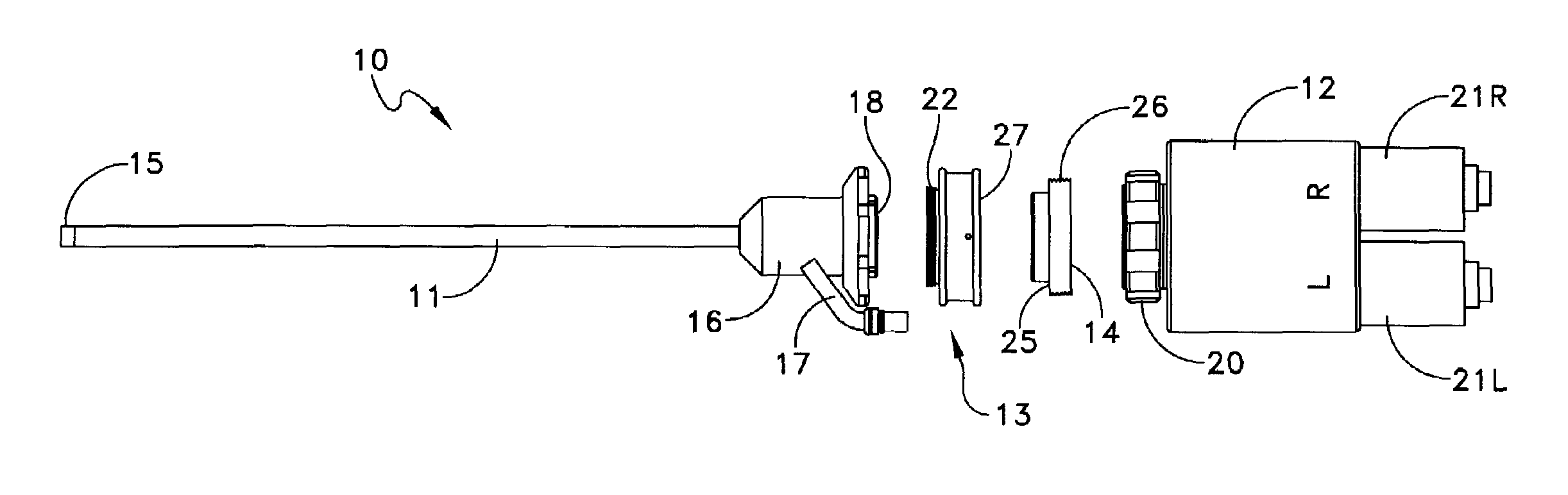
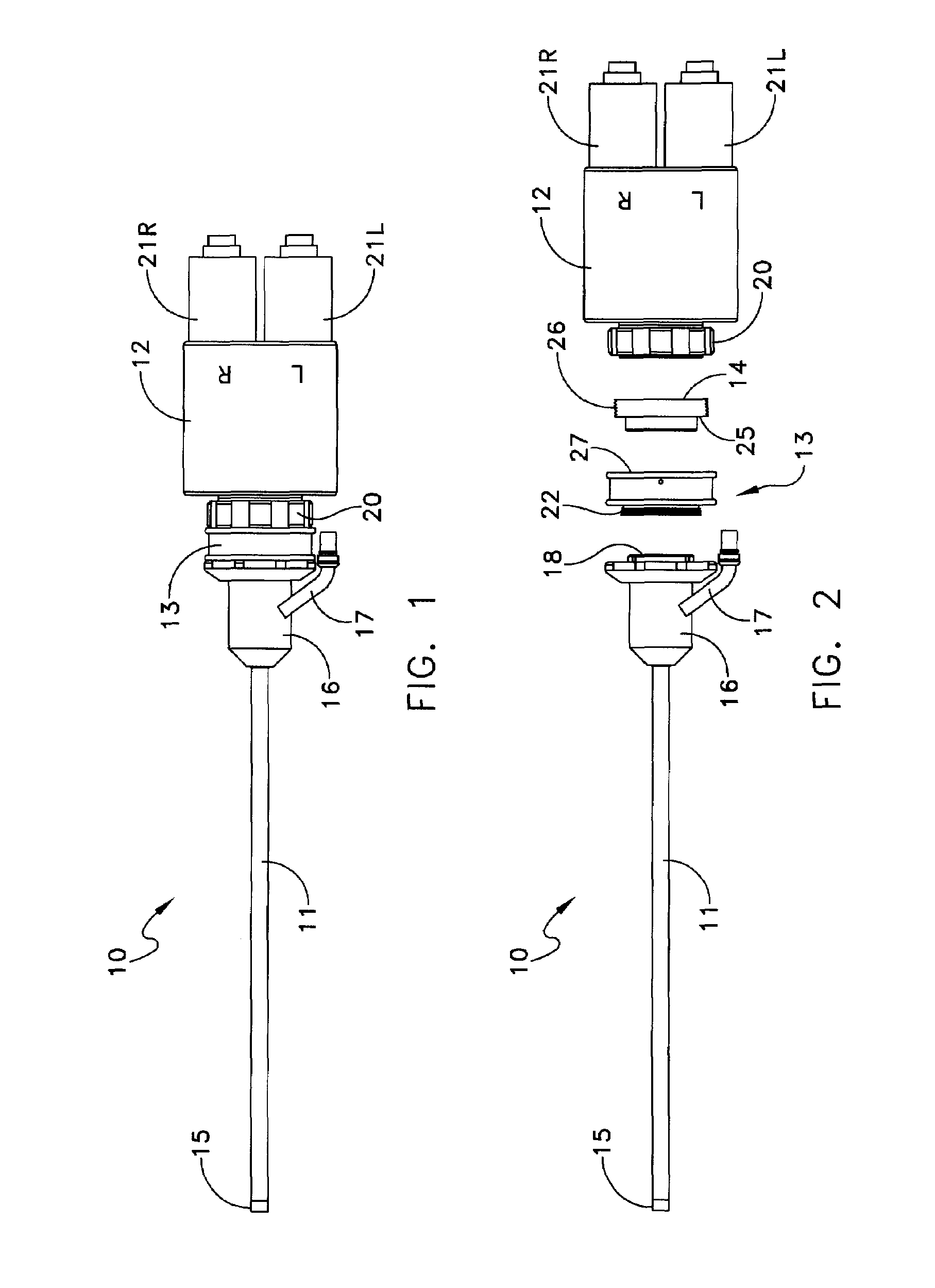
[0028]As shown in FIGS. 1 and 2, an endoscope assembly 10, as an example of an optical stereoscopic system incorporating this invention, includes an endoscope 11 as an imaging system, a camera assembly 12 representing a viewing system, an adapter 13 and a convergence coupler 14. The endoscope 11 carries an objective lens at a distal end 15, relay lenses and an ocular device at the proximal end 16. A light pipe connection 17 provides a means for connecting to a light source to provide illumination at the distal end 15 to illuminate an object. The proximal end 16 also includes an externally threaded coupling 18.

[0029]The camera assembly 12 included in a viewing system can take many forms. In this specific embodiment, the camera assembly 12 includes a front end coupling 20 and left and right cameras 21L and 21R. Internal camera optical elements accept collimated light from the ocular device 13 and flip and focus images onto the light sensitive detectors to produce electronic signals th...


PUM


Abstract

A convergence prism assembly with a housing and a prism structure having a plurality of prisms mounted in a unitary assembly.

Description

FIELD OF THE INVENTION[0001]This invention generally relates to convergence optics used in stereoscopic imaging and viewing systems and more particularly to convergence optics useful with endoscopes that facilitate three-dimensional, or stereoscopic, viewing.DESCRIPTION OF RELATED ART[0002]Endoscopes are examples of imaging systems that have attained great acceptance within the medical community in connection with a number of procedures. This acceptance exists because an endoscope provides a mechanism for performing procedures with minimal patient trauma while enabling a physician to view directly the internal anatomy of a patient. Over the years a number of endoscopes have been developed and have been categorized according to specific applications. Many have specific names including arthroscopes, cystoscopes, proctoscopes, laparoscopes and laryngoscopes. Industrial endoscopes are often called borescopes.[0003]In whatever specific form, endoscopes and other similar imaging systems g...

Claims


Application Information

Patent Timeline
Patent Type & Authority Patents(United States)
IPC IPC(8): A61B1/06A61B1/00G02B23/24G02B25/00
CPCA61B1/00188A61B1/00193G02B25/001G02B23/2415A61B1/00195A61B1/00G02B23/24
Inventor BREIDENTHAL, ROBERT S.CYR, RICHARD G.DAVID, CHRISTOPHERFORKEY, JOSEPH N.FORKEY, RICHARD E.ROSS, ROBERT N.VOLK, BRIAN E.
Owner INTUITIVE SURGICAL OPERATIONS INC
Why Eureka
Try Eureka