Method for concurrent thermal spray and cooling hole cleaning

a cooling hole and thermal spray technology, applied in the direction of sustainable transportation, coating, plasma technique, etc., can solve the problems of overspray that partially or completely blocks the cooling hole of components, high cycle time, low productivity, etc., to reduce the reduction of wall thickness, improve the effect of debris removal, and reduce the effect of component quality

Active Publication Date: 2009-11-24
GENERAL ELECTRIC CO
View PDF24 Cites 21 Cited by
  • Summary
  • Abstract
  • Description
  • Claims
  • Application Information

AI Technical Summary

Benefits of technology

[0011]Yet another advantage of the invention is that concurrent cleaning of cooling holes with thermal spraying permits cleaning overspray from the holes while the applied barrier coating constituents are still warm and pliable, increasing the effectiveness of debris removal over comparable cleaning techniques used after the TBC and the component to which the TBC was applied have substantially cooled and hardened.
[0012]Still another advantage is that component quality may be improved by minimizing wall reduction in the cooling hole.

Problems solved by technology

However, the thermal spray process often results in overspray that partially or completely blocks the component's cooling holes.
As a result, present thermal spray and cleaning processes involve a multi-step, highly labor intensive process of applying a partial layer of TBC coating, allowing the component and the TBC to sufficiently cool to a temperature at which the component can easily be handled, removing the component from an application fixture on which the thermal spraying takes place, and removing any masking, which is then followed by separately removing the well-cooled, solidified coating from the cooling holes using a water jet or other cleaning methods.
This complex process results in low productivity, high cycle time, and increases costs by a factor of five to ten times that of applying the same TBC to a similar non-holed part.

Method used


Image

  • Method for concurrent thermal spray and cooling hole cleaning
  • Method for concurrent thermal spray and cooling hole cleaning
  • Method for concurrent thermal spray and cooling hole cleaning

Examples


Embodiment Construction

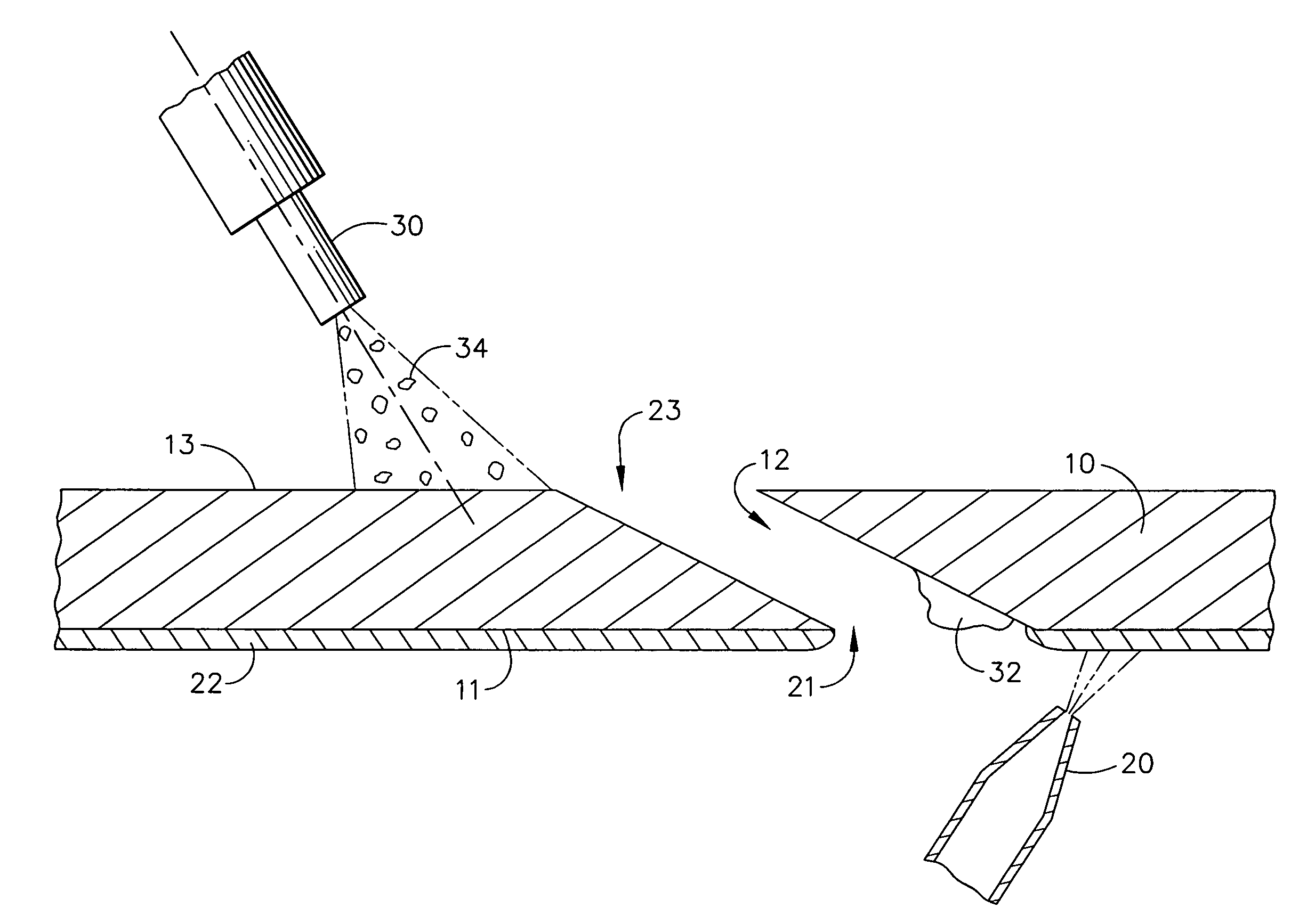
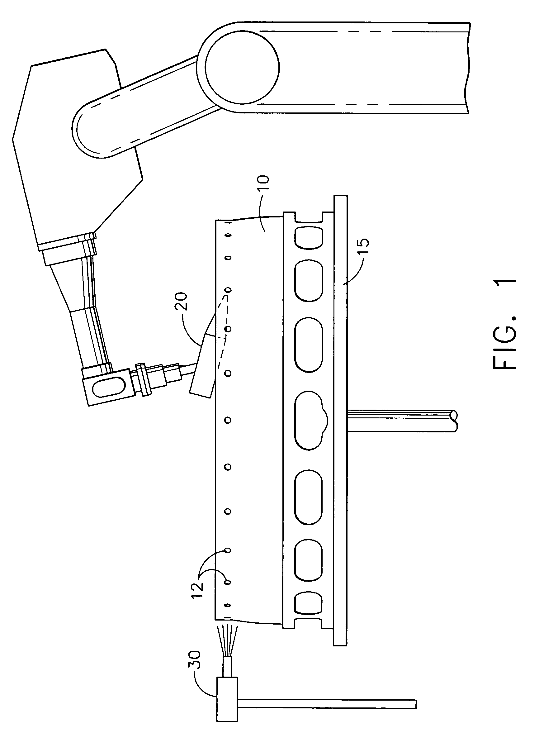
[0019]Referring to FIG. 1, an article 10 having cooling holes 12, such as a combustor liner or other component of a gas turbine engine is provided to which a TBC or other coating may be applied by thermal spray. A thermal spray device 20 is positioned to apply a TBC 22 to the inner surface of the combustor liner 10 (see FIG. 2). An abrasive non-metallic particle blaster (i.e. grit blaster) 30 is positioned to direct grit or other particles toward the outer surface of the combustor liner 10 and into the cooling holes 12. A rotatable table 15 may provide relative movement between the thermal spray device 20, the grit blaster 30, and the combustor liner 10.

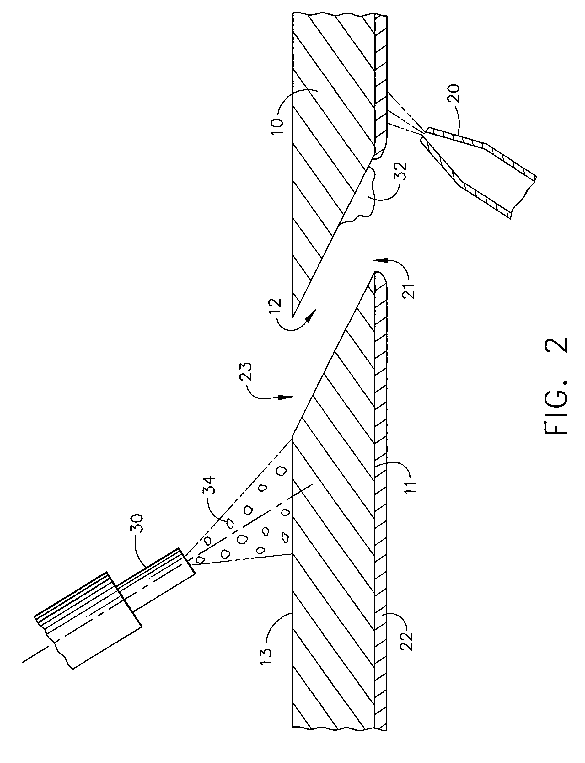
[0020]As better seen with reference to FIG. 2, the cooling holes 12 extend from an opening 21 in a first surface 11 of the combustor liner 10 to which a TBC 22 is applied to a second opening 23 in a second surface 13 of the combustor liner 10.

[0021]The TBC 22 comprises one or more layers of metal and / or ceramic coating material appli...


PUM

PropertyMeasurementUnit
pressureaaaaaaaaaa
angleaaaaaaaaaa
thicknessaaaaaaaaaa

Abstract

A method for applying a thermal barrier coating to an article having cooling holes and concurrently cleaning obstructions, such as TBC overspray or other debris, from those holes is disclosed. A thermal barrier coating is applied to a first surface of an article having cooling holes. Concurrently therewith, a plurality of particles are projected against a second surface of the article, such that at least some of the particles pass through the cooling holes, strike the overspray constituents prior to cooling, knocking at least some of the obstructions out of the cooling hole.

Description

FIELD OF THE INVENTION[0001]The present invention is directed to methods of applying a thermal spray coating to an article having one or more cooling holes and more particularly to methods of thermal spraying an article having one or more cooling holes and cleaning the cooling holes of the article to remove obstructions resulting from overspray or other debris of thermal spraying.BACKGROUND OF THE INVENTION[0002]In gas turbine engines, such as aircraft engines for example, air is drawn into the front of the engine, compressed by a shaft-mounted rotary-type compressor, and mixed with fuel. The mixture is burned, and the hot exhaust gases are passed through a turbine mounted on the same shaft as the compressor. The flow of gas turns the turbine, which turns the shaft and drives the compressor and fan. The hot exhaust gases flow through the engine nozzle at the back of the engine, generating thrust to propel the aircraft forward.[0003]During operation of gas turbine engines, the temper...

Claims


Application Information

Patent Timeline
Patent Type & Authority Patents(United States)
IPC IPC(8): B05D1/32C23C4/00C23C4/06C23C4/10
CPCC23C4/005C23C4/105C23C4/085B23P2700/06Y02T50/67C23C4/01C23C4/073C23C4/11Y02T50/60
Inventor GUPTA, BHUPENDRA K.HEIDORN, RAYTOMLINSON, TOMGLEVICKY, MARK MMOERTLE, GEORGE EHOLLAND, THOMAS GEORGE
Owner GENERAL ELECTRIC CO
Why Eureka
Try Eureka