Engine control apparatus and related engine control method

a control apparatus and engine technology, applied in the direction of engine starters, electric control, machines/engines, etc., can solve the problems of long maximum time, long maximum time, and failure to achieve the effect of reliable start-up and increase reliability

Active Publication Date: 2009-12-08
DENSO CORP
View PDF32 Cites 17 Cited by
  • Summary
  • Abstract
  • Description
  • Claims
  • Application Information

AI Technical Summary

Benefits of technology

[0023]Thus, the engine control apparatus of such a structure can address various issues encountered in the related art. That is, under a circumstance where any of the crank signal and the cam signal encounters a failure and is not normally input, the operation is executed to reliably avoid the drive time limiting means from forcibly interrupting the driving of the starter device before the engine enters the running state. This allows the engine to reliably start up.
[0026]With the engine control apparatus of such a structure, the limit time setting means may be operative to set the limit time to a predetermined initial value until either the first cylinder discriminating means or the second cylinder discriminating means completes the execution of the cylinder discrimination after which when the first cylinder discriminating means and the second cylinder discriminating means complete the execution of the cylinder discrimination, the limit time setting means freshens the limit time to be set to a first time for a normal signal mode to be shorter than the initial value in the absence of the failure in either the crank signal or the cam signal and freshens the limit time to be set to a second time for a failure signal mode to be shorter than the initial value but to be longer than the first time for the normal signal mode, in the presence of the failure in either the crank signal or the cam signal.
[0030]With the engine control apparatus mentioned above, the limit time setting means may be operative to detect specified information related to startability of the engine from among information relevant to the vehicle and set the limit time depending on a detection value on the specified information such that the lower the startability of the engine represented by the detection value, that is, the harder the engine to be started, the longer will be the limit time. This allows the limit time to be set to an optimum value (not to be too long or not to be too short) at all times, providing increased reliability of starting up the engine.
[0035]Therefore, even such an engine control apparatus makes it possible to reliably avoid the driving of the starter device from being forcibly interrupted before the engine enters the running state in the presence of the failure in either the crank signal or the cam signal. This enables the engine to reliably start up.
[0039]Due to a capability of setting the limit time depending on specified information relevant to startability of the engine, the structure including the limit time calculating means may further include the failure mode startup required time calculating means and the setting means. Such a structure enables a condition to be established as “limit time>Ts”. That is, the engine control apparatus of the second aspect of the present invention can be easily applied to a structure that includes the limit time calculating means whose calculated value is set to be the limit time.
[0047]This allows the engine to reliably start up. Moreover, when the failure detecting means detects the failure in either the crank signal or the cam signal, the value of the limit time to be set by the limit time setting means may suffice to have a longer time than the reference time as set forth above. This results in a further increase in reliability in starting up the engine. Accordingly, no battery death or deterioration of the battery takes place in the vehicle when controlled with the method of the present invention mentioned above.

Problems solved by technology

Further, a failure tends to occur in either the crank signal or the cam signal with no variation in signal level due to the disconnection of a sensor signal line or short-circuiting to a specified voltage potential.
That is, with the driving duration time reaching the limit time, the drive of the starter motor is interrupted due to a limiting function resulting from the limit time even if the engine does not enter the running state.
Therefore, this results in a long maximum time from timing at which the cranking of the engine begins, due to the starter motor being driven, to timing at which the cylinder discrimination is completed.
When this takes place, the driving of the starter motor is interrupted, causing a probability with a difficulty of starting up the engine.
Especially, under extremely cold environments, a drop occurs in battery voltage and a viscosity of lubricating oil increases.
This causes a further increase to occur in time for the starter motor to begin in operation to complete the cylinder discrimination, resulting in a further increase in a probability for the startup of the engine to be disabled.

Method used


Image

  • Engine control apparatus and related engine control method
  • Engine control apparatus and related engine control method
  • Engine control apparatus and related engine control method

Examples


first embodiment

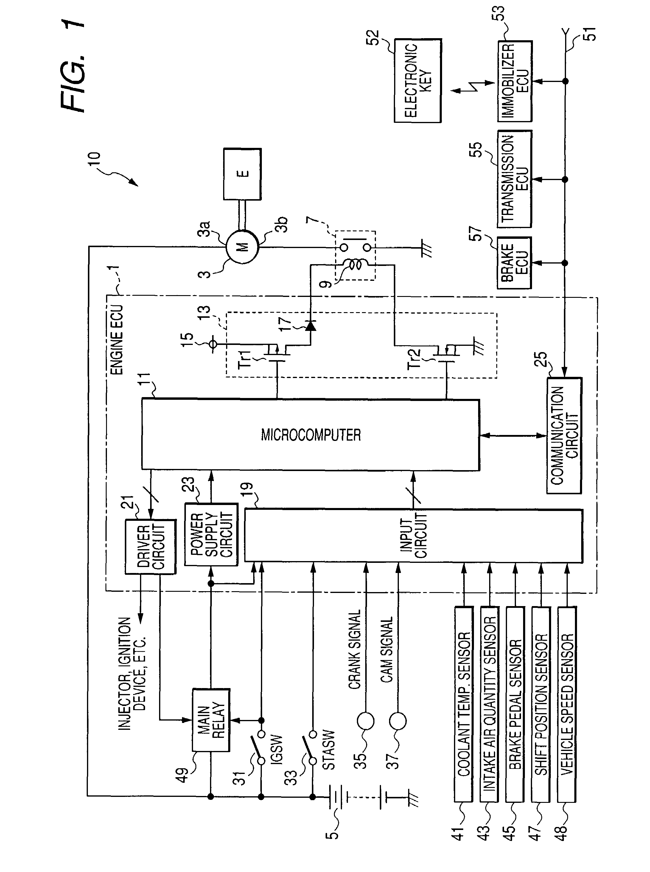
[0061]FIG. 1 is a block diagram showing a structural view of an engine control apparatus 10 of the present embodiment including an engine ECU1 and associated peripheral units. In the illustrated embodiment, the engine ECU1 serves to control a multi-cylinder engine (a six-cylinder engine in the illustrated embodiment) installed on a vehicle. That is, the engine ECU1 performs operations for controlling fuel injection and ignition for each cylinder while additionally performing autostart control to start up the engine upon one-touch operation.

[0062]As shown in FIG. 1, the engine control apparatus 10 includes a starter motor 3 located outside the engine ECU 1 for cranking up a multi-cylinder engine E for startup thereof. The starter motor 3 has a positive terminal 3a connected to a positive terminal of an on-vehicle battery 5 at all times. The starter motor 3 also has a negative terminal 3b connected through a contact of a starter relay 7 to a ground line at “0” volt to which a negative...

second embodiment

[0158]Next, an engine ECU of a second embodiment according to the present invention will be described below. The engine ECU of the second embodiment has the same hardware structure as that of the engine ECU 1 of the first embodiment and the same component parts as those of the first embodiment bear like reference numerals to simplify the description. This similarly applies to other embodiment that will be described later.

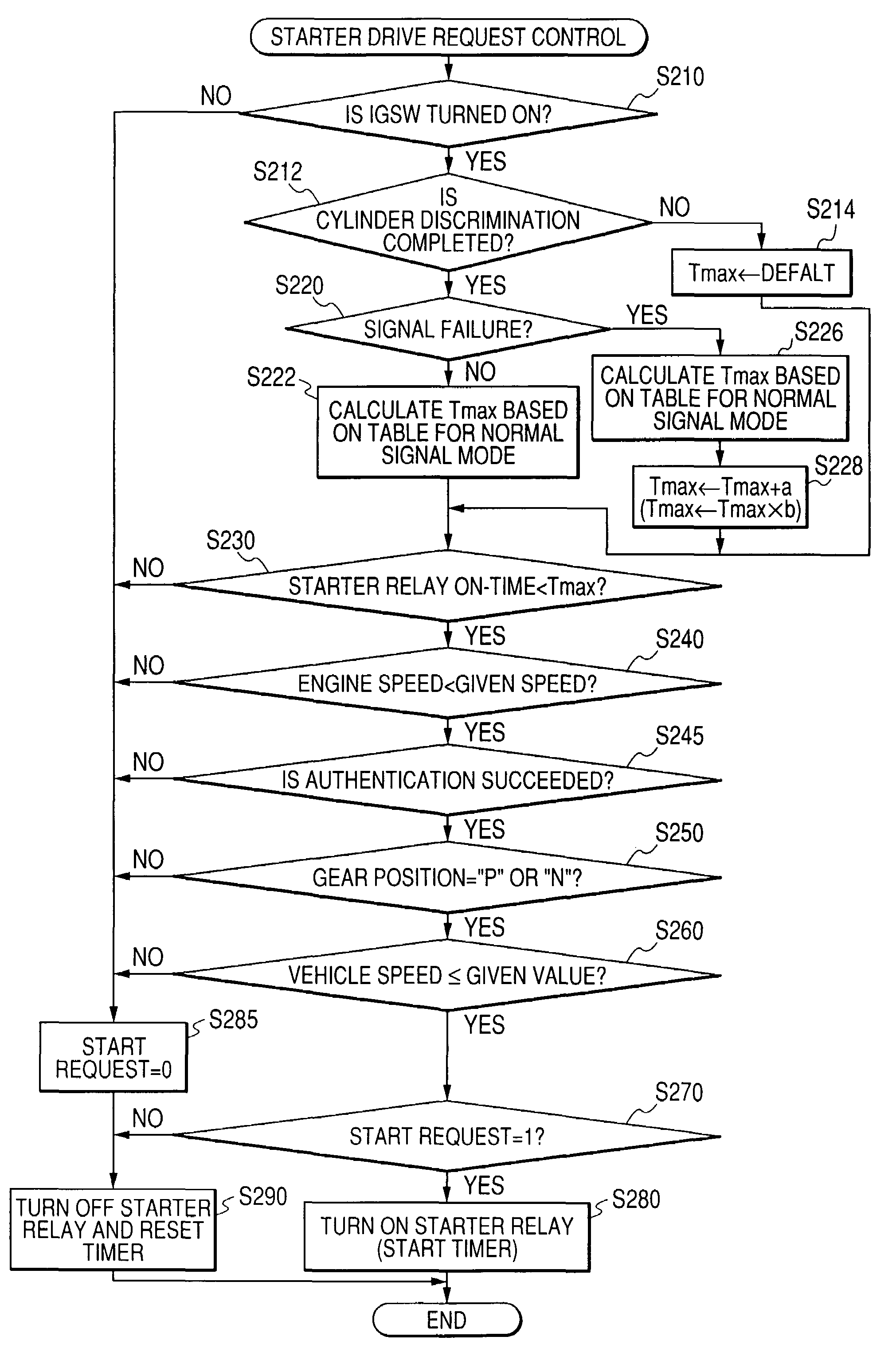
[0159]The engine ECU 1 of the second embodiment differs from that of the first embodiment in that the non-volatile memory of the microcomputer 11 does not store the data table for the failure signal mode and that the microcomputer 11 executes a starter relay drive controlling operation, shown in FIG. 10, in place of the operation shown in FIG. 4.

[0160]In addition, the starter relay drive controlling operation, shown in FIG. 10, differs from the operation, shown in FIG. 4, in that the microcomputer 11 executes operations in S226 and S228 in place of S224.

[0161]In par...

third embodiment

[0166]Next, an engine ECU of a third embodiment according to the present invention will be described below.

[0167]The engine ECU 1 of the third embodiment differs from the engine ECU 1 of the first embodiment in that the non-volatile memory of the microcomputer 11 does not store the data table for the failure signal mode but stores a data table (hereinafter referred to as “failure mode startup required time calculation table”), in place of the above data table, for calculating a startup required time Ts for the failure signal mode. In addition, the failure mode startup required time calculation table has data plotted in terms of the coolant water temperature and the startup required time Ts for the failure signal mode in a manner similar to the solid line L3 shown in FIG. 7.

[0168]Further, with the engine ECU 1 of the third embodiment, the microcomputer 11 executes the starter relay drive controlling operation, shown in FIG. 11, in place of the operation shown in FIG. 4.

[0169]The star...


PUM


Abstract

An engine control apparatus and related control method for an engine are disclosed wherein cylinder discrimination is executed based on a crank signal and a cam signal under a normal signal mode. If a failure occurs in either the crank signal or the cam signal, the cylinder discrimination is executed based on a normal one of the crank signal and the cam signal. A starter device is driven to crank up the engine until judgment is made that the engine enters a running state. A duration time for the starter device to be driven is measured and if the duration time reaches a limit time, the driving state of the starter device is interrupted. When either the crank signal or the cam signal encounters the failure, the limit time is set to a longer time than a preset time for the normal signal mode.

Description

CROSS REFERENCE TO RELATED APPLICATIONS[0001]This application is related to Japanese Patent Application No. No. 2006-119710, filed on Apr. 24, 2006, the content of which is hereby incorporated by reference.BACKGROUND OF THE INVENTION[0002]1. Technical Field of the Invention[0003]The present invention relates to engine control apparatuses for vehicles and, more particularly, to an engine control apparatus and a related engine control method for controlling autostart (automatic startup) of an engine of a vehicle.[0004]2. Description of the Related Art[0005]In the related art, attempts have heretofore been made to provide engine control apparatuses for controlling startups of multi-cylinder engines installed on vehicles as disclosed in, for instance, Japanese Patent Application Publication No. 2003-254147 (Patent Publication 1) and Japanese Patent Application Publication No. 2003-49696 (Patent Publication 2).[0006]Each of these multi-cylinder engines generally includes a crank sensor a...

Claims


Application Information

Patent Timeline
Patent Type & Authority Patents(United States)
IPC IPC(8): F02D45/00F02D41/06F02N99/00
CPCF02D41/009F02D41/061F02D41/222F02N11/0848Y02T10/40F02N11/0818F02D2041/0092
Inventor ANDO, KATSUYUKI
Owner DENSO CORP
Why Eureka
Try Eureka