Photonic crystal structure sensor

a technology of photonic crystal structure and sensor, applied in the field of optical fiber compatible sensor systems, can solve the problems of not being able to respond well to frequencies above a few hundred hz, and be bulky, so as to improve the temperature stability of the acoustic sensor

Active Publication Date: 2009-12-08
THE BOARD OF TRUSTEES OF THE LELAND STANFORD JUNIOR UNIV
View PDF20 Cites 54 Cited by
  • Summary
  • Abstract
  • Description
  • Claims
  • Application Information

AI Technical Summary

Benefits of technology

[0014]In certain embodiments, a method of fabricating an acoustic sensor is provided. The method comprises providing at least one photonic crystal structure. The method further comprises optically coupling an end of an optical fiber to the at least one photonic crystal structure. The method further comprises providing a structural portion and mechanically coupling the structural portion to the at least one photonic crystal structure and to the optical fiber. A distance between the at least one photonic crystal structure and the end of the optical fiber is selected to improve a temperature stability of the acoustic sensor.

Problems solved by technology

A current limitation of acoustic fiber sensors is that in order to be highly sensitive, they require a long length of fiber, which makes them bulky and poorly to non-responsive to frequencies above a few hundred Hz.

Method used


Image

  • Photonic crystal structure sensor
  • Photonic crystal structure sensor
  • Photonic crystal structure sensor

Examples


Embodiment Construction

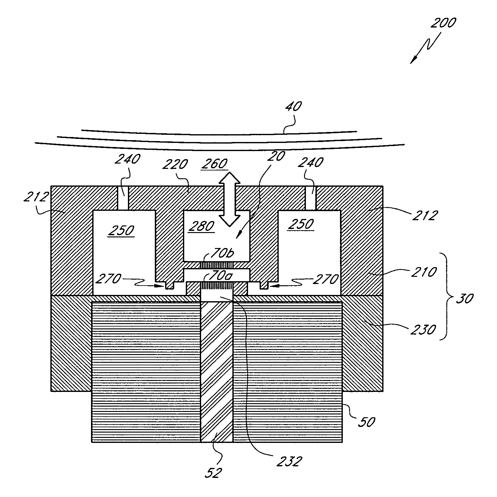
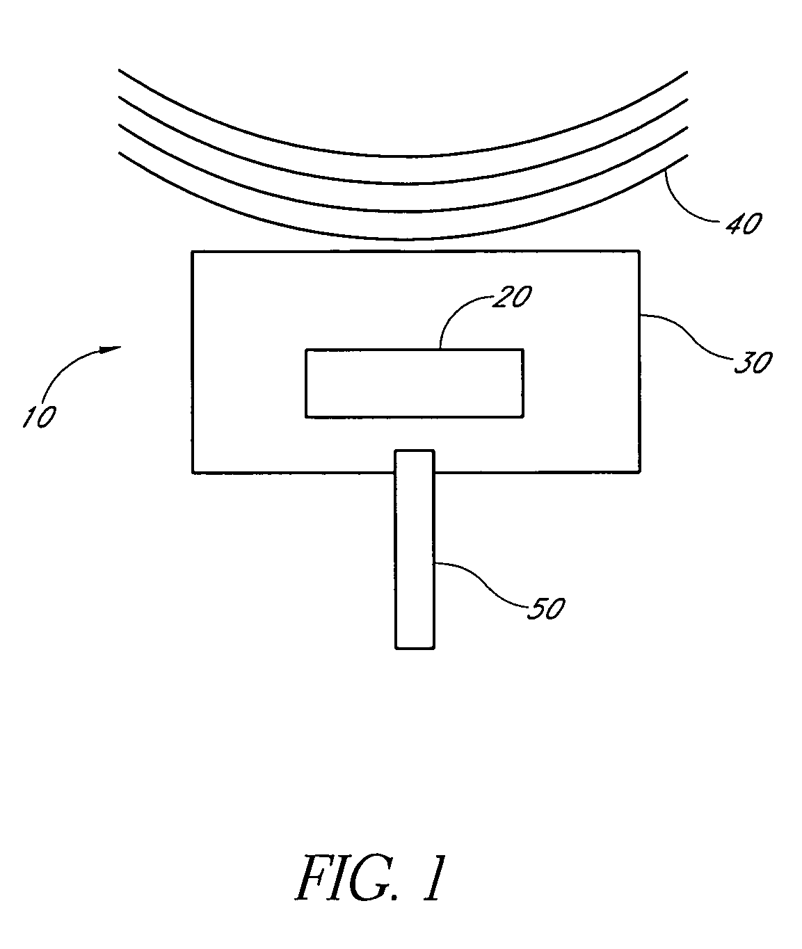
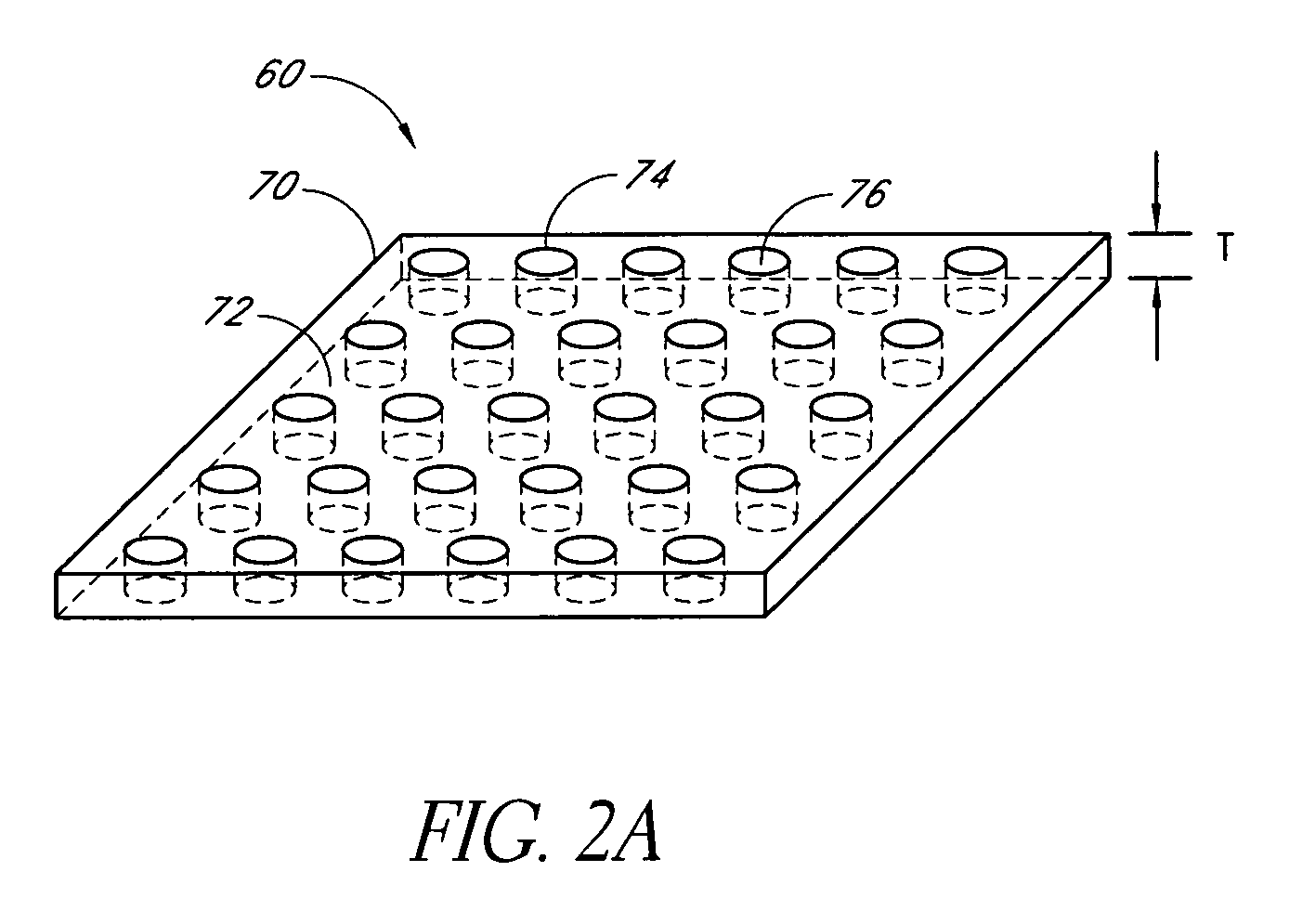
[0094]Present-day optical resonators which have sufficient quality factors to achieve sensitivities comparable to those of piezoelectric transducers are typically large and impractical to fabricate, install, align, and operate. In contrast, certain embodiments described herein comprise an acoustic sensor based on optical resonators formed by photonic crystal slab (PCS) structures with apertures which are orders of magnitude smaller than those of traditional optical cavities. The small size of certain such embodiments provides a sensitivity comparable to that of piezoelectric and capacitive displacement sensors for frequencies larger than about 10 kHz. Photonic crystal structures comprising a pair of PCSs can be used to provide notch and bandpass transmission and reflection filters, and such structures can be utilized in acoustic sensor systems compatible with various applications (e.g. oil exploration, undersea acoustic wave detection).

[0095]Certain embodiments described herein prov...


PUM

PropertyMeasurementUnit
acoustic frequenciesaaaaaaaaaa

Abstract

An acoustic sensor and a method of fabricating an acoustic sensor are provided. The acoustic sensor includes at least one photonic crystal structure and an optical fiber having an end optically coupled to the at least one photonic crystal structure. The acoustic sensor further includes a structural portion mechanically coupled to the at least one photonic crystal structure and to the optical fiber. The at least one photonic crystal structure, the optical fiber, and the structural portion substantially bound a region having a volume such that a frequency response of the acoustic sensor is generally flat in a range of acoustic frequencies.

Description

CLAIM OF PRIORITY[0001]This application claims the benefit of U.S. Provisional Patent Application No. 60 / 879,465, filed Jan. 9, 2007, which is incorporated in its entirety by reference herein, and U.S. Provisional Patent Application No. 61 / 000,003, filed Oct. 23, 2007, which is incorporated in its entirety by reference herein.BACKGROUND OF THE INVENTION[0002]1. Field of the Invention[0003]This application relates generally to sensor systems, and more particularly to optical-fiber-compatible sensor systems.[0004]2. Description of the Related Art[0005]Fiber-optic acoustic sensors have been extensively researched since their first emergence in the 1970s (see, e.g. J. H. Cole, R. L. Johnson, and P. G. Bhuta, “Fiber-optic detection of sound,” J. Acoust. Soc. Am. Vol. 62, 1136 (1977); J. A. Bucaro, H. D. Dardy, and E. F. Carome, “Fiber-optic hydrophone,” J. Acoust. Soc. Am. Vol. 62, 1302 (1977)), largely because of their multiple advantages over conventional acoustic sensors. These advant...

Claims


Application Information

Patent Timeline
Patent Type & Authority Patents(United States)
IPC IPC(8): G02B6/00
CPCG01H9/004G02B6/264Y10T29/49826
Inventor KILIC, ONURDIGONNET, MICHEL J. F.KINO, GORDON S.SOLGAARD, OLAVBASU MALLICK, SHRESTHAAKKAYA, ONUR CAN
Owner THE BOARD OF TRUSTEES OF THE LELAND STANFORD JUNIOR UNIV
Why Eureka
Try Eureka