Dry etching apparatus capable of monitoring motion of WAP ring thereof

a technology of wap ring and etching apparatus, which is applied in the direction of electric discharge tubes, instruments, plumb lines for surveying, etc., can solve the problems of affecting the quality of wap ring, the size of the wap ring b>16/b>, and the fatigue of springs or worn rollers or parts, so as to prevent particle contamination of the chamber or the wafer

Active Publication Date: 2009-12-15
UNITED MICROELECTRONICS CORP
View PDF12 Cites 5 Cited by
  • Summary
  • Abstract
  • Description
  • Claims
  • Application Information

AI Technical Summary

Benefits of technology

[0010]It is one object of the present invention to provide an alarm and monitor system to detect the abnormal motion of each of the plunger shafts during descending and ascending of the WAP ring, thereby preventing particle contamination of the chamber or wafer.

Problems solved by technology

One drawback of the above-described prior art is that a gap 18 between the top electrode 14 and the WAP ring 16 is very small, which is typically about 0.02 inch or less.
The discrepancy between the three plunger shafts 32 may result from fatigue of the spring or worn rollers or parts.

Method used


Image

  • Dry etching apparatus capable of monitoring motion of WAP ring thereof
  • Dry etching apparatus capable of monitoring motion of WAP ring thereof
  • Dry etching apparatus capable of monitoring motion of WAP ring thereof

Examples


Embodiment Construction

[0022]The present invention will now be described in more detail hereinafter with reference to the accompanying drawings. In the drawings, the size and relative position of the elements of the dry etching apparatus are exaggerated for the sake of clarity. Furthermore, like numeral numbers refer to like elements throughout the drawings.

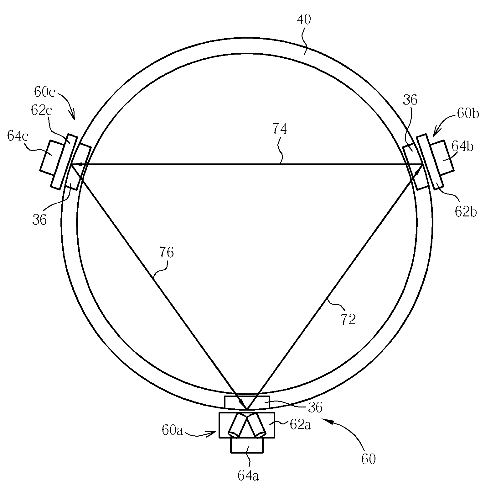
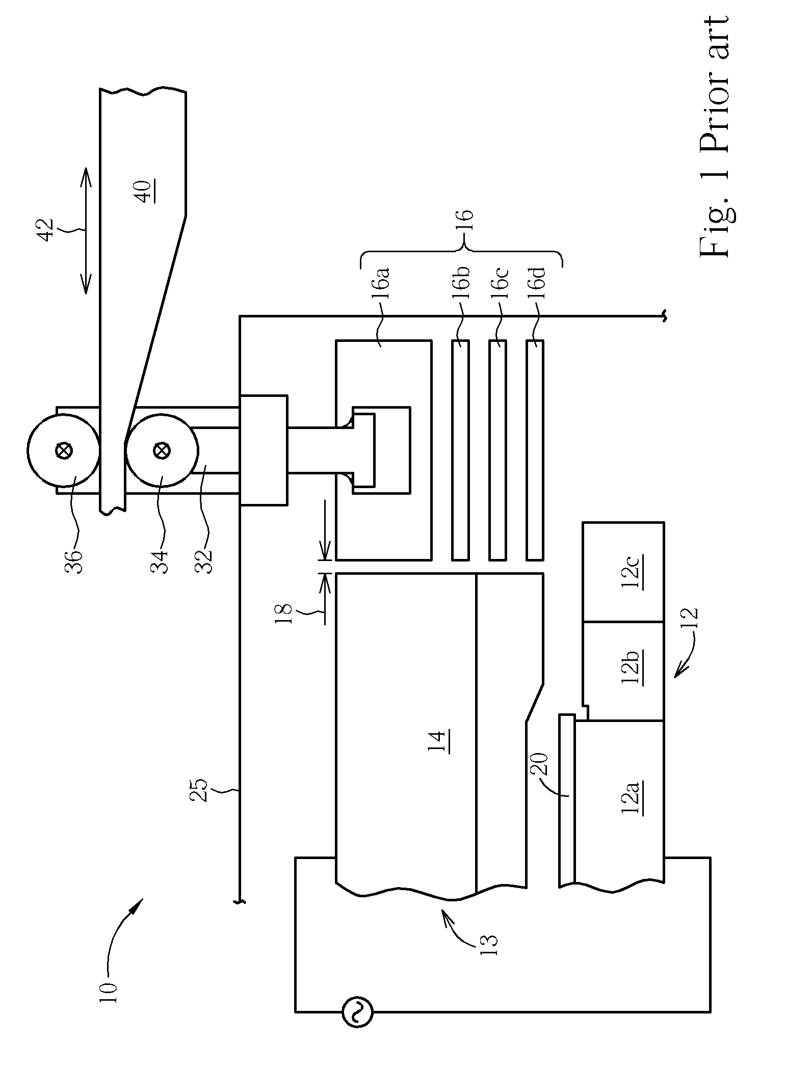
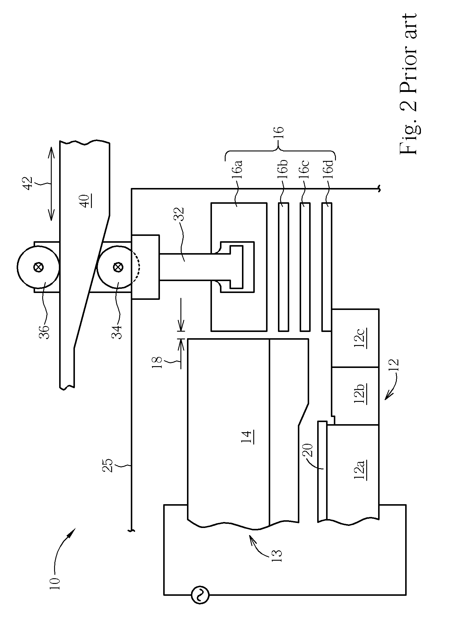
[0023]Please refer to FIG. 3. FIG. 3 is a schematic, cross-sectional diagram illustrating the arrangement of WAP ring, plunger shaft and optical monitoring system of a dry etching apparatus in accordance with one preferred embodiment of this invention. The dry etching apparatus 100 comprises a lower assembly 12 and an upper portion 13. Both the lower assembly 12 and the upper portion 13 are installed in a chamber housing 25.

[0024]The lower assembly 12 generally includes a disk-shaped electrostatic chuck (ESC) 12a, a focus ring 12b, and a ground ring 12c. The ESC 12a is capable of holding a wafer 20 and is typically serves as a bottom electrode or anode...


PUM

PropertyMeasurementUnit
optical pathaaaaaaaaaa
resilientaaaaaaaaaa
pressureaaaaaaaaaa

Abstract

An optical monitoring system includes a ring-shaped object suspended by and engaged with a plurality of vertical plunger shafts. Normally, the vertical plunger shafts move upward and downward reciprocally and coherently, but independently, such that the ring-shaped object ascends or descends horizontally. A light transceiver device is affixed to one vertical plunger shaft. A plurality optical reflector elements are affixed to respective other plunger shafts. A light beam emanated from said light transceiver is reflected by the optical reflector elements and is eventually re-directed back to the light transceiver device.

Description

BACKGROUND OF THE INVENTION[0001]1. Field of the Invention[0002]The present invention relates generally to an apparatus for manufacturing a semiconductor device and, more particularly, to a dry etching apparatus capable of monitoring the motion of the wafer area pressure (WAP) ring and the plunger shafts that actuate the WAP ring.[0003]2. Description of the Prior Art[0004]Plasma etching has become the preferred technique for etching patterns in the various layers utilized in the manufacture of integrated circuit devices. The apparatus for such etching typically includes a chamber housing a pair of essentially planar electrodes that are spaced apart in a parallel relationship to define an interaction space therebetween. On a lower electrode is positioned a semiconductor wafer being processed. For such processing, an appropriate gaseous medium is introduced into the chamber and then one or more suitable high radio-frequency voltages are impressed across the pair of electrodes to gener...

Claims


Application Information

Patent Timeline
Patent Type & Authority Patents(United States)
IPC IPC(8): C23F1/00
CPCH01L21/67069H01J37/32935Y10S156/915
Inventor LAI, SHYH-KUEN
Owner UNITED MICROELECTRONICS CORP
Why Eureka
Try Eureka