Device for processing a component, carriage for the device, and method for operating the device

a technology for components and devices, applied in the direction of conveyers, transportation and packaging, propulsion systems, etc., can solve the problems of deterioration of vacuum quality, high cost, and complex device structur

Active Publication Date: 2019-10-31
SCIA SYST GMBH
View PDF2 Cites 3 Cited by
  • Summary
  • Abstract
  • Description
  • Claims
  • Application Information

AI Technical Summary

Benefits of technology

[0007]With the present invention, an apparatus for processing a component, a travel carriage for such a device and a method for operating such a device are provided which at least alleviates some of the aforementioned disadvantages or even completely avoids them.

Problems solved by technology

However, in the case of lines running within the process chambers, outgassing may occur under vacuum and may thereby lead to foreign material contamination and / or particulate contamination of the vacuum and thus deterioration of the vacuum quality (e.g. the minimum pressure achievable by a particular configuration of the apparatus) and of the processing result of the component.
In addition, the lines connected to the conventional traversing device are particularly hindering the transition from areas of different pressure levels (e.g. the transition from atmosphere side to the vacuum side) and usually additional, detachable connections and lines must be provided to the drive system on the vacuum side to provide energy from the atmosphere side, which causes a more complex structure of the device and thus high costs and high workload in manufacturing and assembly of the conventional device.
Further, different drive systems are usually used in different sections (for example, on the atmosphere side, vacuum side, etc.) of the device, which makes a modularized construction of the conventional devices difficult and also leads to high costs and high labor content involved in the manufacture and assembly of conventional devices.

Method used


Image

  • Device for processing a component, carriage for the device, and method for operating the device
  • Device for processing a component, carriage for the device, and method for operating the device
  • Device for processing a component, carriage for the device, and method for operating the device

Examples


Embodiment Construction

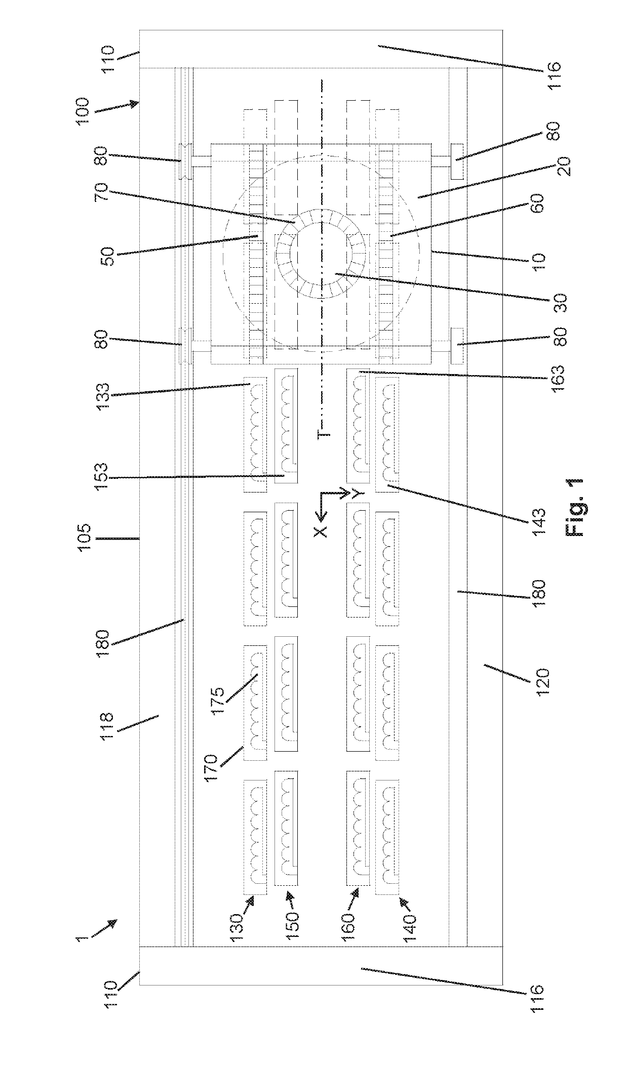
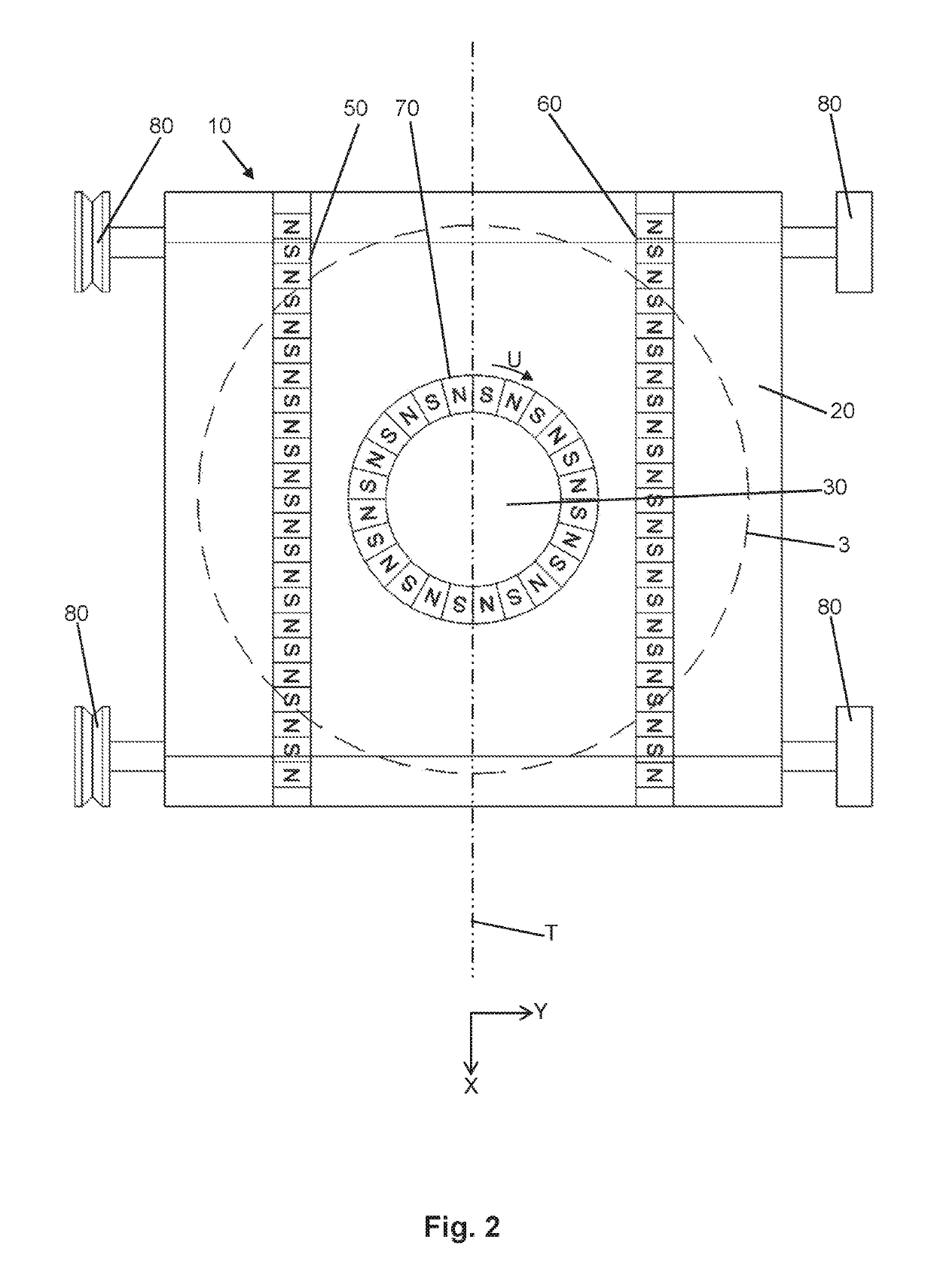
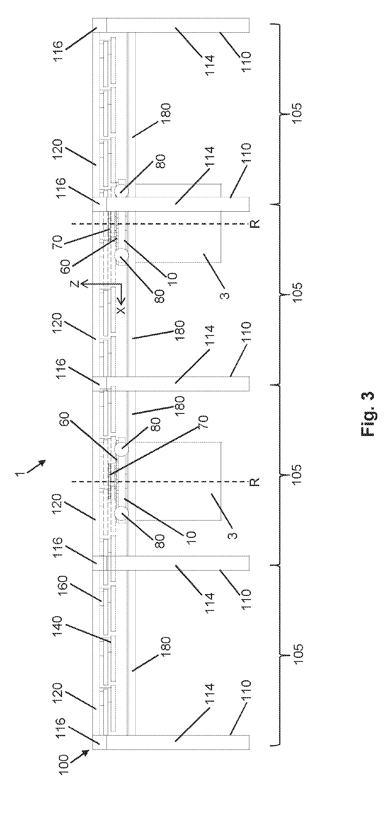
[0060]In the following detailed description, reference is made to the accompanying drawings, which form a part hereof, and in which specific embodiments in which the invention may be used are shown by way of illustration. In this regard, directional terminology such as “top”, “bottom”, “front”, “back”, “forward”, “backward”, etc. is used with reference to the orientation of the described figure(s). Since components of examples and embodiments can be positioned in a number of different orientations, the directional terminology is illustrative and is in no way limiting. It should be understood that other examples and embodiments may be utilized, and structural or logical changes may be made without departing from the scope of the present invention. It should be understood that the features of the various examples and embodiments described herein may be combined with each other unless specifically stated otherwise. The following detailed description is therefore not to be taken in a li...


PUM

PropertyMeasurementUnit
temperatureaaaaaaaaaa
magneticaaaaaaaaaa
braking forceaaaaaaaaaa

Abstract

The present invention relates to a device for processing a component, comprising: a travel carriage having a frame which defines an axis of translation along which the travel carriage is translationally movable, a bogie which is relatively rotatably connected to the frame and to which the component is attachable, a first translation-permanent magnet device which is mounted on the frame and having permanent magnets, a rotation-permanent magnet device attached to the bogie and having permanent magnets, and a carriage-side longitudinal guide means mounted on the frame, a stationary travel carriage guide device having a guide-side longitudinal guide means, a first electromagnet translation device with electromagnets which magnetically interact with the permanent magnets of the first translation-permanent magnet device, a first rotation-electromagnet device having electromagnets which magnetically interact with the permanent magnets of the rotation-permanent magnet device, and a controller connected to the first translating electromagnet device and to the first rotation-electromagnet device to control its electromagnets to control the translational movement of the travel carriage and the rotational movement of the bogie.

Description

FIELD OF THE INVENTION[0001]The present invention relates to an apparatus for processing (for example for coating and / or stripping) a component and a travel carriage for such a device and a method for operating such a device.BACKGROUND OF THE INVENTION[0002]Generally, conventional devices are used for coating and / or stripping, generally used for processing a component to apply one or more layers of material of desired thickness on a component and / or remove them from it. Usually, such conventional devices have a number of chambers / stations, into which and / or through which the component is transported, in order to be subjected to certain processing operations. For example, the component is transported from an atmosphere side into a process chamber in which a vacuum predominates and in which the necessary machining operations, for example for coating the component or for removing material from the component, are carried out. After completion of the processing operations, the component ...

Claims


Application Information

Patent Timeline
Patent Type & Authority Applications(United States)
IPC IPC(8): B05B13/02B65G54/02H02K5/20H02K41/03
CPCB05B13/0235H02K5/20H02K41/033B65G54/02H02K41/031H02K2201/18H02K5/203C23C14/568H01J37/32733
Inventor HAUSTEIN, DANIELMARTIN, SYBILLENESTLER, MATTHIASZEUNER, MICHAEL
Owner SCIA SYST GMBH
Why Eureka
Try Eureka