DC-based data center power architecture

a data center and power architecture technology, applied in the field of power distribution systems, can solve the problems of significant waste of energy resources, drive up the cost of operating data centers, and culprits of power consumption, so as to achieve the effect of reducing monthly power costs, ensuring server reliability, and ensuring reliability

Active Publication Date: 2009-12-15
EYP MISSION CRITICAL +1
View PDF11 Cites 26 Cited by
  • Summary
  • Abstract
  • Description
  • Claims
  • Application Information

AI Technical Summary

Benefits of technology

[0012]Unlike traditional rack servers, today's leading rack-mount and open blade servers can be powered with a vastly more reliable DC power. DC power supplies achieve efficiency levels of 93% at the component level, compared to 70% efficiency in traditional AC power supplies. In addition, by distributing redundant DC power to each server, approximately 20% to 40% of the thermal load is shifted outside the server to AC-to-DC rectifiers. As a result, server reliability can be increased by as much as 27%, and monthly power costs can be reduced by as much as 30%.

Problems solved by technology

As availability requirements (i.e., the amount of uptime) placed on data centers increase, these issues will continue to drive up the costs associated with operating data centers.
One of the main culprits of this power consumption lies in the fact that most data centers rely on AC to power the servers and other equipment.
Traditional AC power supplies operate at about a 70% efficiency level, which results in a significant waste of energy resources.
In addition to providing relatively low power efficiency, such configurations also generate a significant amount of heat that must be dealt with.
Unfortunately, no DC-based architectural infrastructure has been developed or proposed that will adequately address the major operational issues faced by data centers.

Method used


Image

  • DC-based data center power architecture
  • DC-based data center power architecture
  • DC-based data center power architecture

Examples


Embodiment Construction

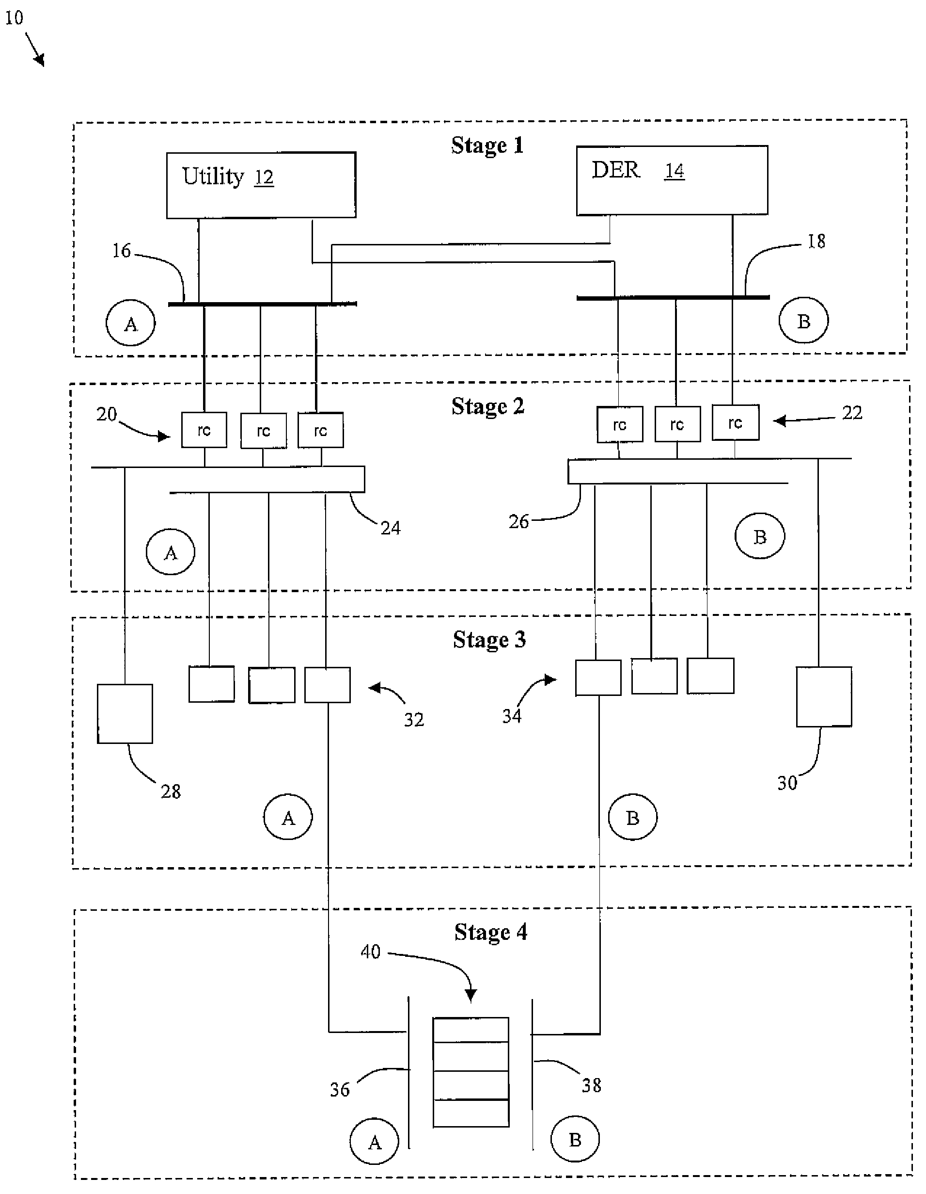
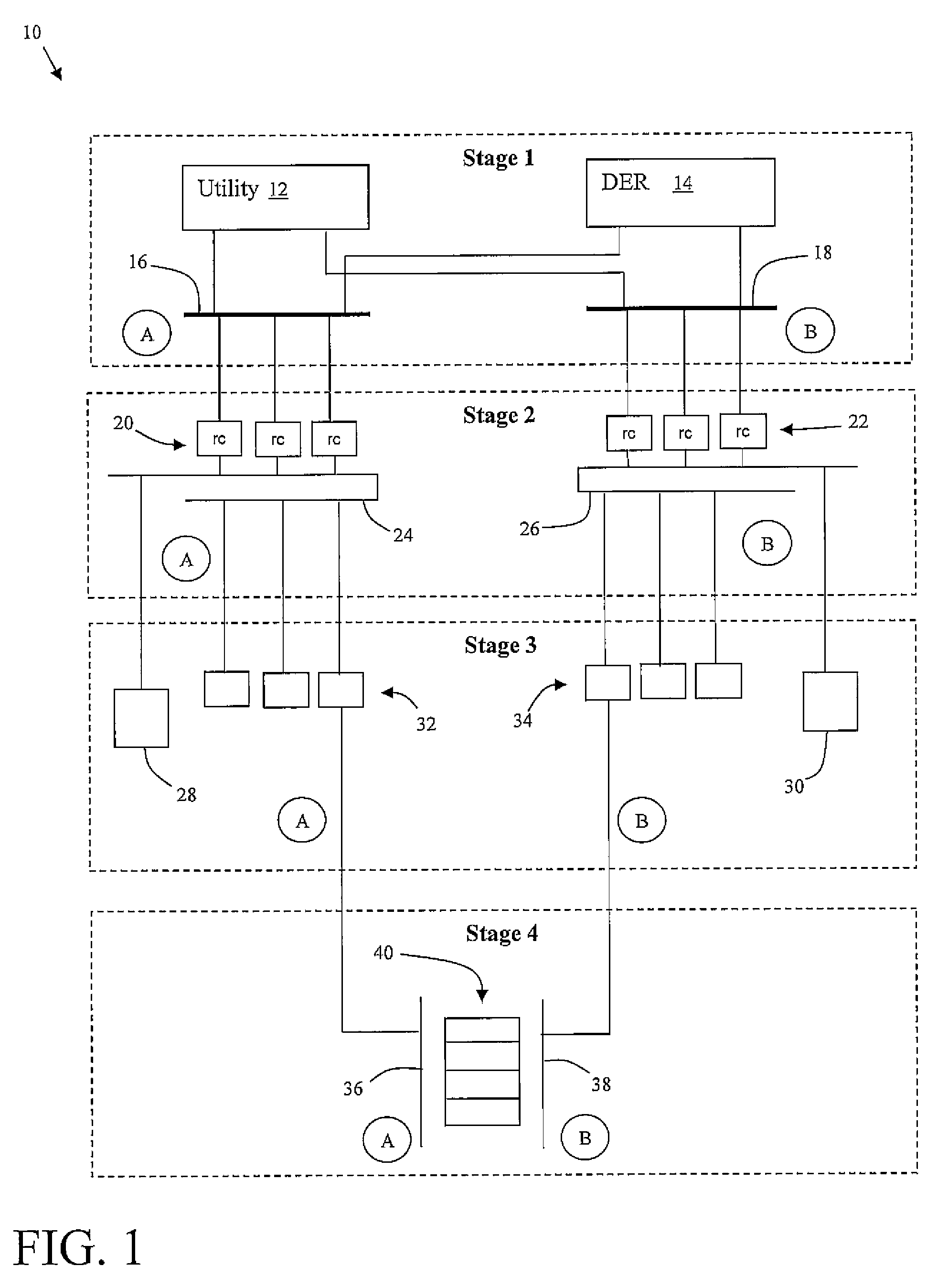
[0020]Referring now to drawings, FIG. 1 depicts an overview of an illustrative DC-based power distribution architecture 10 for powering critical loads 40 in a data center. Critical loads 40 are the main loads of a data center and include, for instance, equipment installed in cabinets (e.g., servers, computing components, etc.), on racks (e.g., telecom equipment such as routers and switches) or directly on the floor (e.g., heavy storage devices, etc.). Mechanical loads (not shown in FIG. 1) are related to HVAC systems, plumbing systems and various other essential loads supporting the critical loads 40. Note that for the purpose of this disclosure the term “data center” may refer to any facility that includes high density devices and / or other systems that run on DC, such as computer systems, servers, telecom equipment, medical equipment, etc.

[0021]Power distribution architecture 10 is shown broken down into four stages. In general, stage 1 provides an AC power distribution system that...


PUM


Abstract

A DC-based power system including: an AC power distribution system for providing AC power to a first node and a second node; a first converting system coupled to the first node that converts AC power to DC power and outputs the DC power to a first distributed bus bar; a second converting system coupled to the second node that converts AC power to DC power and outputs the DC power to a second distributed bus bar; a first set of DC / DC converters that steps down the DC power from the first distributed bus bar to a first stepped down DC voltage; a second set of DC / DC converters that steps down the DC power from the second distributed bus bar to a second stepped down DC voltage; and a critical load distribution system that is powered by both the first stepped down DC voltage and the second stepped down DC voltage.

Description

RELATED APPLICATION[0001]This application claims priority to co-pending provisional application entitled DC2 CONCEPT, filed on Jun. 2, 2005, Ser. No. 60 / 686,633, the content of which is hereby incorporated by reference.FIELD OF THE INVENTION[0002]The invention relates generally to power distribution systems, and more particularly, to a DC-based architecture for powering data centers.BACKGROUND OF THE INVENTION[0003]With the advent of the information technology age, data center have become critical to the operation of almost all large scaled enterprises. Illustrative enterprises that rely on data centers include: financial service companies, government agencies, defense operations, hospitals, commercial Websites, etc. As the need to accommodate and process more and more data grows, greater and greater demands are placed onto the infrastructure of the data center.[0004]Issues that must be addressed include: providing an infrastructure that can maintain 24 / 7 operations; controlling the...

Claims


Application Information

Patent Timeline
Patent Type & Authority Patents(United States)
IPC IPC(8): H02J9/00H02J1/10H02J3/00
CPCH02J5/00H02J9/06H02J7/02
Inventor GROSS, PETERGODRICH, KFIR
Owner EYP MISSION CRITICAL
Why Eureka
Try Eureka