Parallel pipeline graphics system

a parallel pipeline and graphics system technology, applied in the field of parallel pipeline graphics system, can solve the problems of moving to a 256 bit system, memory bandwidth becomes a limitation on performance, and the back-end of the graphics chip is currently inadequa

Active Publication Date: 2009-12-15
ATI TECH INC
View PDF53 Cites 111 Cited by
  • Summary
  • Abstract
  • Description
  • Claims
  • Application Information

AI Technical Summary

Benefits of technology

[0017]In some embodiments, four parallel pipelines or other pipeline configurations having 2^n pipelines may be used. Each pipeline is a component of a raster back-end, where the display screen is divided into tiles and a defined portion of the screen (i.e., one or more tiles) is sent through a pipeline that owns that portion of the screen's tiles.
[0018]In one embodiment, each parallel pipeline comprises a raster back-end having a scan converter to step through the geometric patterns passed to the back-end, a “hierarchical-Z” component to

Problems solved by technology

As will be further described below, graphics chip back-ends are currently inadequate.
When processing three-dimensional data, memory bandwidth becomes a limitation on performance.
Moving to a 256 bit system, where 512 bits

Method used


Image

  • Parallel pipeline graphics system
  • Parallel pipeline graphics system
  • Parallel pipeline graphics system

Examples


Embodiment Construction

[0035]The invention relates to a parallel pipeline graphics system. In the following description, numerous specific details are set forth to provide a more thorough description of embodiments of the invention. It will be apparent, however, to one skilled in the art, that the invention may be practiced without these specific details. In other instances, well known features have not been described in detail so as not to obscure the invention.

[0036]Parallel Array Graphics System

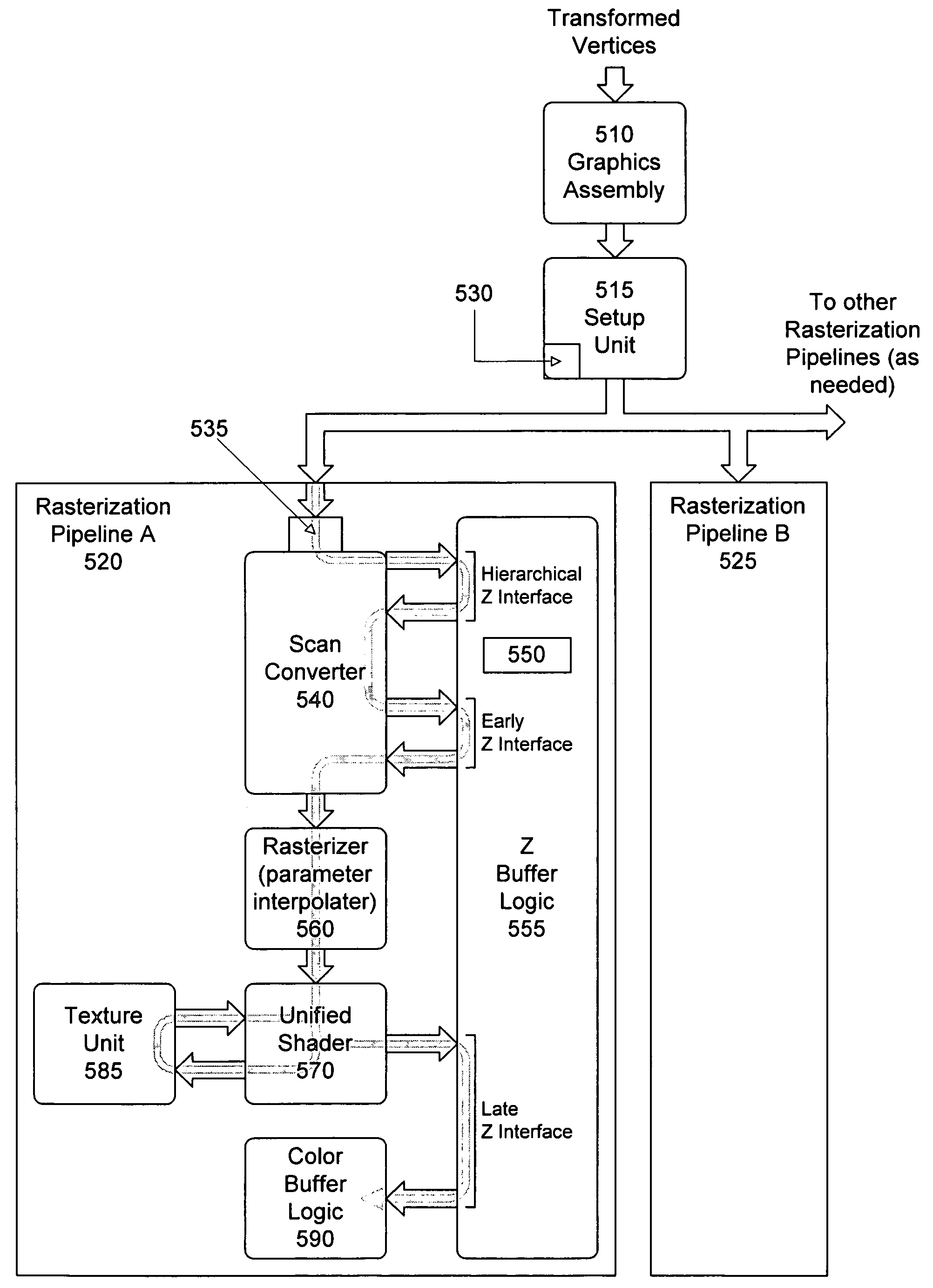
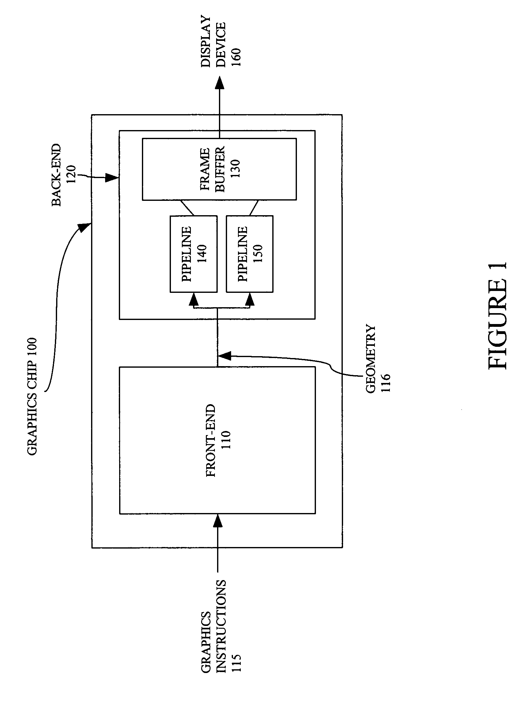
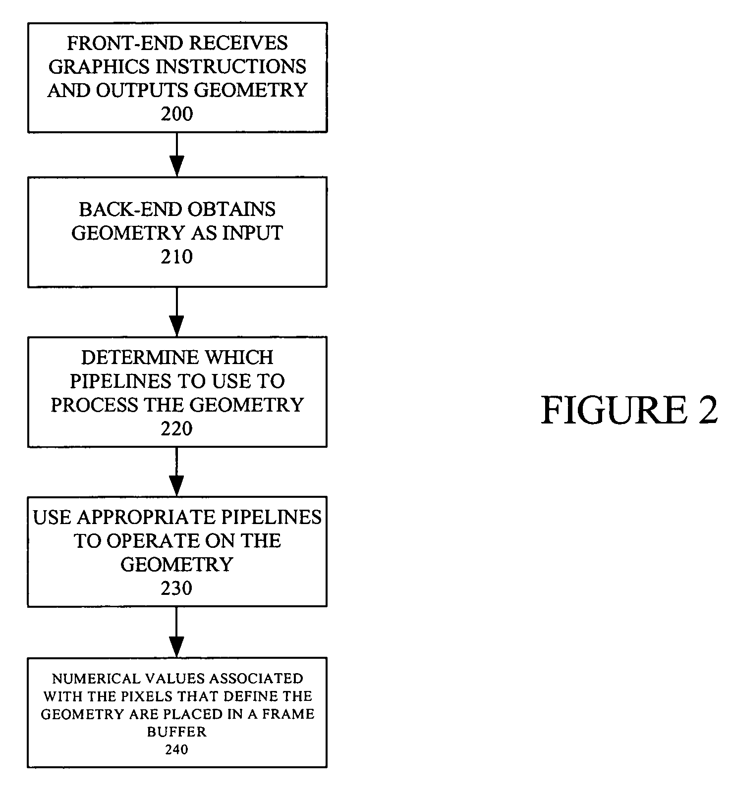
[0037]One embodiment of the present invention is shown in the block diagram of FIG. 1. Graphics processing chip 100 comprises a front-end 110 and a back end 120. The front-end 110 receives graphics instructions 115 as input and generates geometry 116 as output. The back-end 120 is used to process the geometry 116 it receives as input. For instance, the back-end 120 might operate by texturing, shading, scanning, coloring, or otherwise preparing a pixel for final output.

[0038]When the geometry 116 has been fully p...


PUM


Abstract

The present invention relates to a parallel pipeline graphics system. The parallel pipeline graphics system includes a back-end configured to receive primitives and combinations of primitives (i.e., geometry) and process the geometry to produce values to place in a frame buffer for rendering on screen. Unlike prior single pipeline implementation, some embodiments use two or four parallel pipelines, though other configurations having 2^n pipelines may be used. When geometry data is sent to the back-end, it is divided up and provided to one of the parallel pipelines. Each pipeline is a component of a raster back-end, where the display screen is divided into tiles and a defined portion of the screen is sent through a pipeline that owns that portion of the screen's tiles. In one embodiment, each pipeline comprises a scan converter, a hierarchical-Z unit, a z buffer logic, a rasterizer, a shader, and a color buffer logic.

Description

[0001]This application claims priority to U.S. Provisional Application No. 60 / 429,976, filed Nov. 27, 2002.[0002]This is a related application to a co-pending U.S. patent application entitled “DIVIDING WORK AMONG MULTIPLE GRAPHICS PIPELINES USING A SUPER-TILING TECHNIQUE”, having Ser. No. 10 / 459,797, filed Jun. 12, 2003, having Leather et al. as the inventors, owned by the same assignee and hereby incorporated by reference in its entirety.BACKGROUND OF THE INVENTION[0003]1. Field of the Invention[0004]The present invention relates computer graphics chips.[0005]Portions of the disclosure of this patent document contain material that is subject to copyright protection. The copyright owner has no objection to the facsimile reproduction by anyone of the patent document or the patent disclosure as it appears in the Patent and Trademark Office file or records, but otherwise reserves all copyright rights whatsoever.[0006]2. Background Art[0007]Computer systems are often used to generate an...

Claims


Application Information

Patent Timeline
IPC IPC(8): G06T1/20
CPCG06T15/005G06T11/40G09G5/393
Inventor LEATHER, MARK M.DEMERS, ERIC
Owner ATI TECH INC
Why Eureka
Try Eureka