Non-image, computer assisted navigation system for joint replacement surgery with modular implant system

a technology of joint replacement and navigation system, applied in the field of computer assisted total hip replacement or hip arthroplasty operations, can solve the problems of wear, deformation or even fracture, many procedures will eventually require revision, extreme pain,

Active Publication Date: 2009-12-15
KINAMED
View PDF13 Cites 121 Cited by
  • Summary
  • Abstract
  • Description
  • Claims
  • Application Information

AI Technical Summary

Benefits of technology

[0012]The system of the invention includes a modular implant system, having a plurality of components, adapted for assembly according to a plurality of assembly options to allow adjustment of the implant geometry. In one embodiment, at least one of the components has one or more index features. During joint replacement surgery (for example, hip replacement surgery) two trackable markers are fixed: one to a first bone (for example, the pelvis) and the other to a second bone (for example, the femur). Optionally, a trackable tool is adapted to be positioned in contact with an index feature. A locating system tracks the two trackable markers (and optionally the trackable tool), and provides positional information which is output to a computer. The computer receives the positional information and digitally models a relationship of the modular joint implant system to the first and second bones of

Problems solved by technology

Many of the procedures will eventually require revision, due to one of any number of problems.
Problems can arise with the implant, which can wear, degrade or even fracture.
In other cases, dislocation of the replaced hip can occur, causing extreme pain (not to mention inconvenience and expense).
In spite of the published research, the typical surgeon has not adopted any sophisticated method of navigating hip replacement surgery, in spite of the availability of several techniques.
This method fails to consider the considerable mov

Method used


Image

  • Non-image, computer assisted navigation system for joint replacement surgery with modular implant system
  • Non-image, computer assisted navigation system for joint replacement surgery with modular implant system
  • Non-image, computer assisted navigation system for joint replacement surgery with modular implant system

Examples


Embodiment Construction

Overview

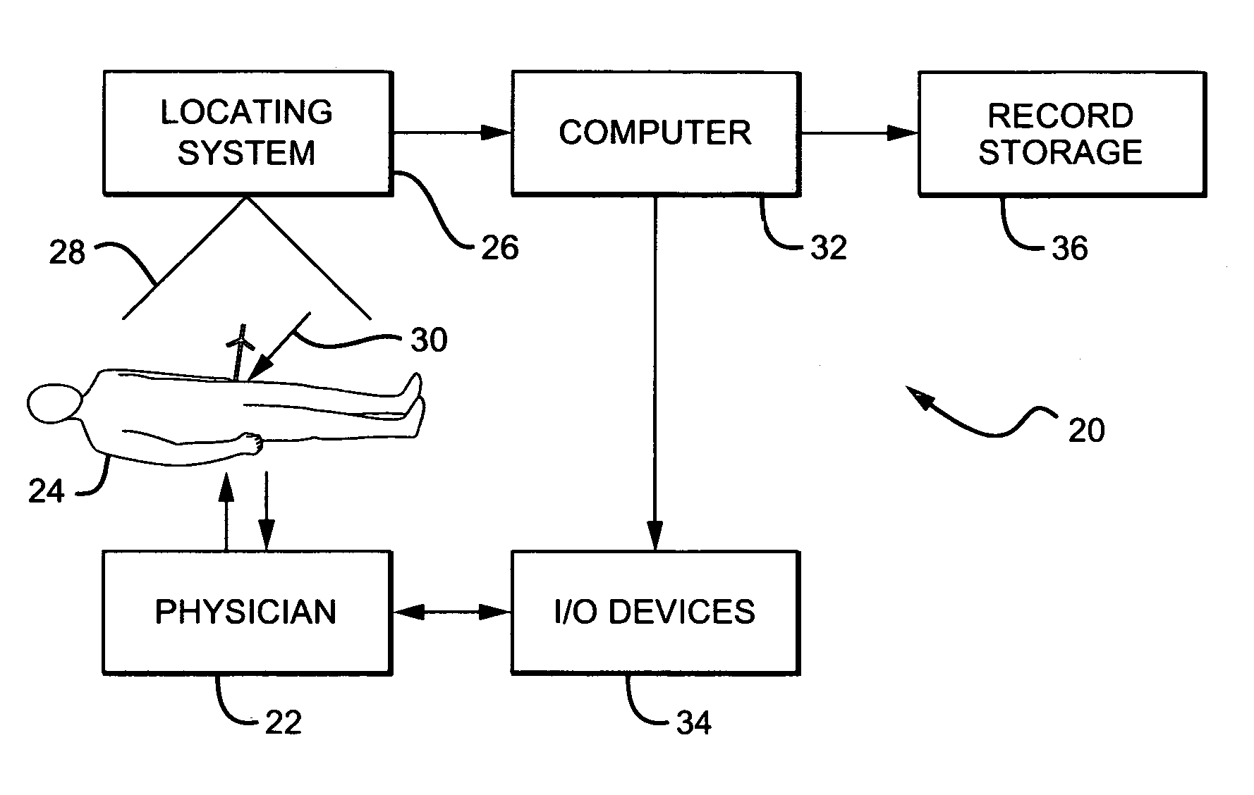
[0035]Throughout the description of the invention, reference will frequently be made to “tracking” or “trackable markers.” This terminology is intended to denote any of several available methods of tracking objects in three dimensions without unwieldy mechanical frameworks or measuring devices. In the most preferred embodiment of the invention, optical tracking is employed, using optically trackable markers such as those available from Traxtal in Toronto, Canada. Similarly, in the description we will refer to a “locating system.” In a preferred embodiment of the invention, the locating system will be an optical, computer aided locating system such as the “Polaris” system available from Northern Digital Inc. in Waterloo, Ontario, Canada. However, it should be understood that other methods of tracking, locating systems, and trackable markers could be employed without departing from the invention. For example, magnetic, electromagnetic, ultrasonic, sonic, infrared, or microwave...


PUM


Abstract

The invention includes a method and system for intra-operative navigation of a joint replacement operation, without recourse to pre-operative imagery of pre-operative computerized simulations. Trackable markers and a locating system are employed to track first and second bones. A computer receives positional information regarding the trackable markers and calculates (predicts) at least one suggested combination of components of a modular implant system to produce a desired post-operative skeletal relationship.

Description

[0001]This application is a continuation-in-part of U.S. patent application Ser. No. 10 / 075,796 filed Feb. 13, 2002, now U.S. Pat. No. 6,711,431 and claims priority of that application as to matter disclosed therein. This application further claims priority of application Ser. No. 10 / 637,304 filed Aug. 8, 2003 (with priority of provisional application 60 / 402,179 filed Aug. 9, 2002) as to matter disclosed therein.BACKGROUND OF THE INVENTION[0002]1. Field of the Invention[0003]This invention relates to computer assisted surgery generally and more specifically to computer assisted total hip replacement (THR) or hip arthroplasty operations.[0004]2. Description of the Related Art[0005]Total hip replacement or arthroplasty operations have become increasingly common in the United States, with more than 300,000 such operations occurring annually. Many of the procedures will eventually require revision, due to one of any number of problems. Problems can arise with the implant, which can wear...

Claims


Application Information

Patent Timeline
IPC IPC(8): A61B5/05A61F2/32A61B5/103A61B19/00A61F2/34A61F2/36A61F2/46G06F
CPCA61B5/103A61B5/4528A61B19/52A61B19/5244A61F2/4609A61F2/4657A61B5/1127A61B5/6878A61B19/50A61B2019/446A61B2019/461A61B2019/502A61B2019/505A61B2019/5255A61B2019/5268A61B2019/5272A61B2019/5483A61F2/34A61F2/4081A61F2/4684A61F2002/4623A61F2002/4632A61F2002/4658A61F2002/4668A61F2/4603A61B34/10A61B34/20A61B90/36A61B90/94A61B2034/102A61B2034/105A61B2034/2055A61B2034/2068A61B2034/2072A61B2090/061A61B2090/3983
Inventor SARIN, VINEET KUMARBRUCE, ROBERT A.PRATT, WILLIAM RALPHPRATT, CLYDE RONALD
Owner KINAMED
Why Eureka
Try Eureka