
Optimal coupling of high performance line imaging spectrometer to imaging system

a high-performance line imaging and imaging system technology, applied in the field of coupling of imaging optical systems, can solve the problems of not being able to take advantage of the array of photodetectors, devices developed before the time, and analyzers were not able to perform simultaneous analysis

Active Publication Date: 2009-12-22
PAWLUCZYK ROMUALD +1
View PDF20 Cites 37 Cited by
  • Summary
  • Abstract
  • Description
  • Claims
  • Application Information

AI Technical Summary

Problems solved by technology

With scale exception, a similar problem arises in microscopy where the distribution of some chemical components across the microscopic samples has to be determined.
In the past such analyzers were not able to perform simultaneous analysis on a number of points so that the analysis was performed consecutively point by point.
The devices developed before the time of the above publication could not take advantages provided by arrays of photodetectors, which did not exist at that time.
As a result, measurement systems of such kind were not able to perform spectral analysis of radiation transformed by the microscopic sample by fluorescence, Raman scattering, phosphorescence or similar effects.
Such a point by a point spectral analysis has many disadvantages and many methods have been developed for simultaneous extraction of spectral information for number of adjacent or non-adjacent points of the object or its image produced by some optical imaging system.
Similar problems exist in all areas of spectroscopy applications, where information on spatial spectral variability of target or sample are required.
This is clear that while such filtering provides valued information, the amount of information obtained in such a way is limited by the number of filters, which can be practically used.

Method used


Image

  • Optimal coupling of high performance line imaging spectrometer to imaging system
  • Optimal coupling of high performance line imaging spectrometer to imaging system
  • Optimal coupling of high performance line imaging spectrometer to imaging system

Examples


Embodiment Construction

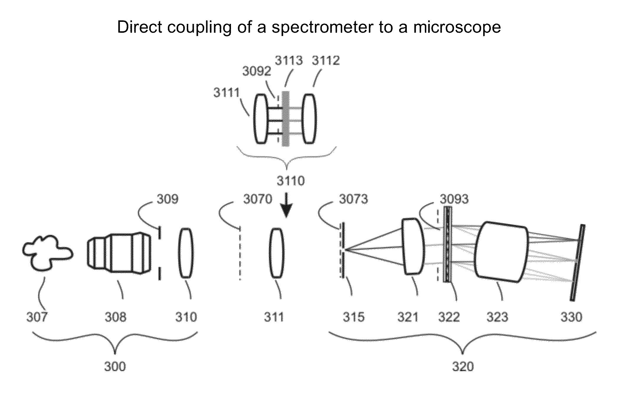
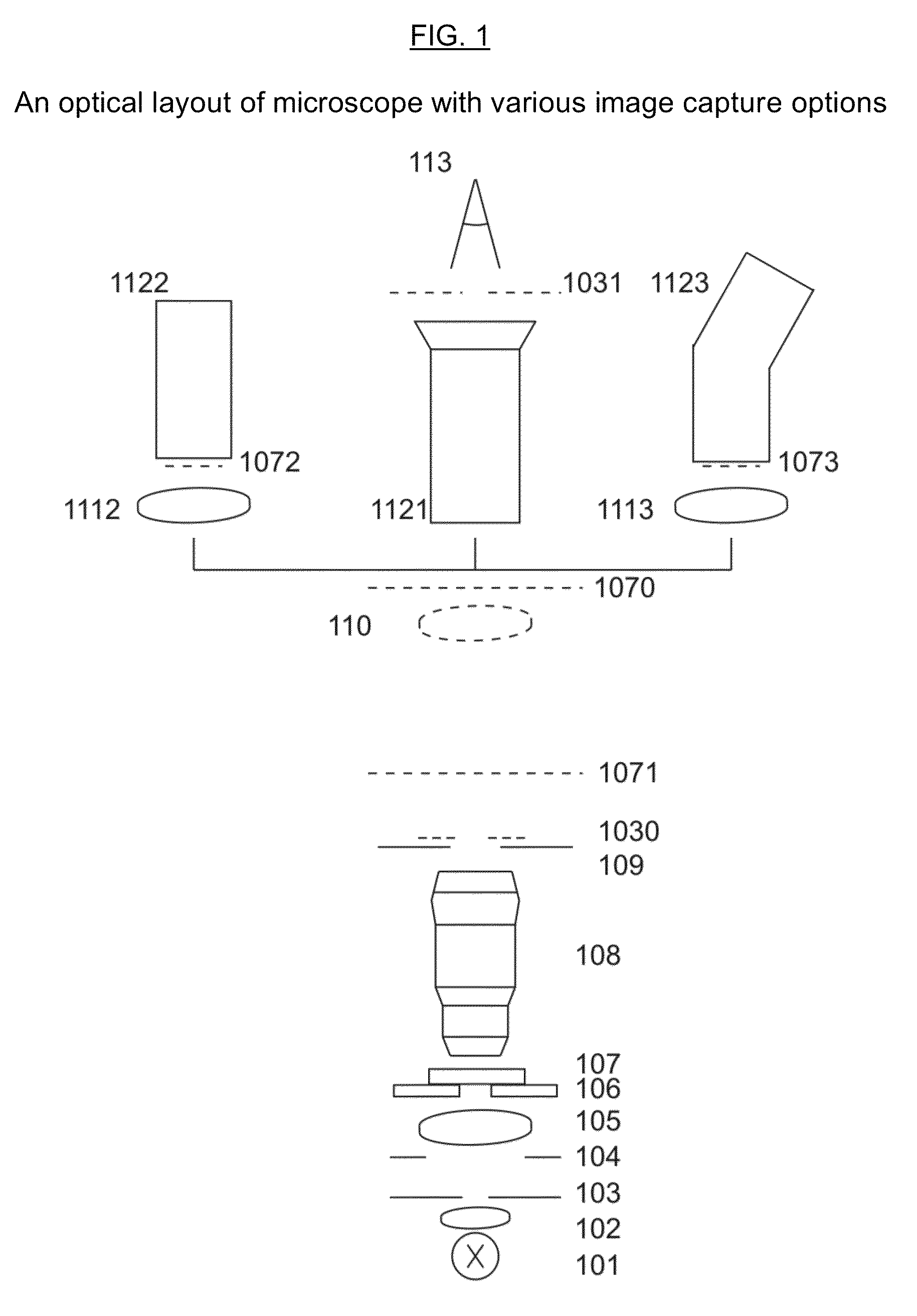
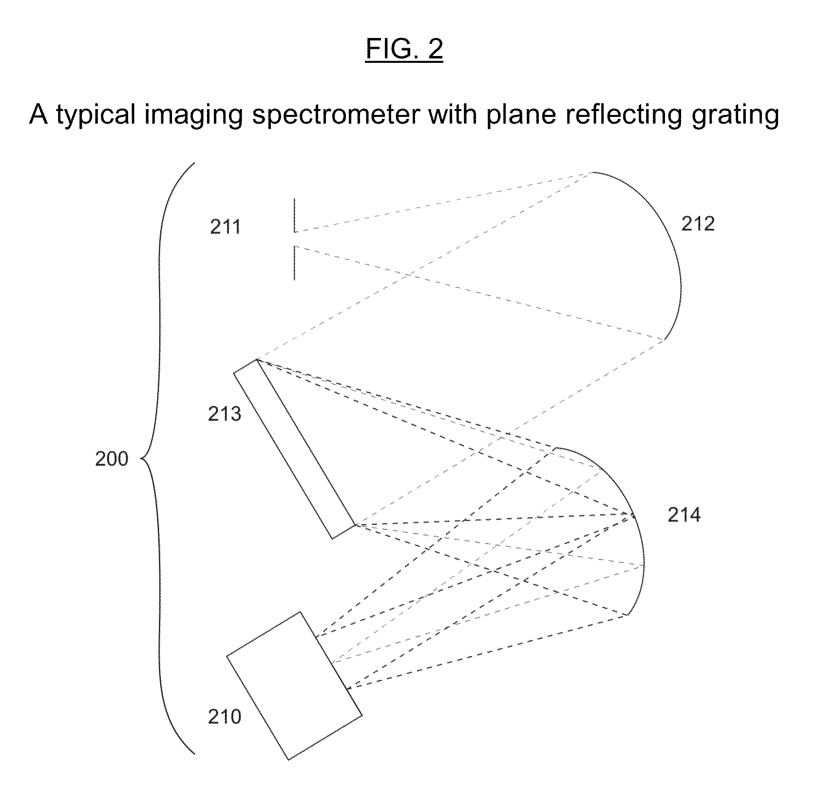
[0021]The present invention provides effective means for coupling an optical imaging system such as telescope, photographic or TV camera objective, microscope or any other imaging system, which creates a real image of the target or sample with some kind of image analyzer, a line imaging spectrometer. Each imaging optical system, predestined for the image registration by some means produces in space, a real image of the sample or target where some kind of image capturing element such as photographic material, photosensitive area of vidicon, array of photodetectors or other similar device is placed to produce technically recognizable physical reaction correlated to spatial intensity distribution of electromagnetic radiation (light). Depending on the situation, the registered image can either be demagnified (TV cameras, photographic cameras, telescopes), registered without change of scale (some photographic and TV cameras) or magnified (microscopes, some photographic and TV cameras). I...


PUM


Abstract

An optical coupling relay system has an imaging optical system having an object plane, an exit pupil and an image plane. An image analyzer has an image plane and an entrance pupil, and a detector is located in a detector plane and contains photosensitive material. An optical coupling relay couples the optical system to the image analyzer, for projecting the image produced by the imaging optical system into the image plane of the image analyzer and simultaneously for projecting the exit pupil of the imaging optical system into the entry pupil of the image analyzer.

Description

PRIORITY CLAIM[0001]This application claims the benefit under 35 USC §119(e) from U.S. provisional patent application Ser. No. 60 / 612,526, filed Sep. 24, 2004.FIELD OF INVENTION[0002]This invention pertains to the field of coupling of an imaging optical system in preferred embodiment microscope to a high performance image analyzing system in preferred embodiment to the line imaging spectrophotometer and, more particularly, to conversion of an ordinary optical imaging system such as a microscope into high performance image analyzing system performing high performance spectral analysis able to perform parallel processing on number of adjacent or non adjacent series of measurement points.BACKGROUND OF THE INVENTION[0003]There is continuously increasing need for precise, non-destructive, non-contact, or remote chemical analysis of selected targets and samples, as well as analysis of distribution of the tested components within the target or sample. This may include identification of che...

Claims


Application Information

Patent Timeline
Patent Type & Authority Patents(United States)
IPC IPC(8): G01J3/02G01J3/28
CPCG01J3/02G01J3/0208G01J3/0218G01J3/024G02B21/002G01J3/0297G01J3/28G01J3/2823G01J3/0291
Inventor PAWLUCZYK, ROMUALDPAWLUCZYK, OLGA
Owner PAWLUCZYK ROMUALD
Learn More