Drive device, particularly for a clockwork mechanism

a drive device and clockwork technology, applied in the field of microelectromechanical systems or electromechanical microsystems, can solve the problems of complex gear mechanism of watches or clocks, and achieve the effect of improving their efficiency

Active Publication Date: 2009-12-22
SILMACH
View PDF13 Cites 23 Cited by
  • Summary
  • Abstract
  • Description
  • Claims
  • Application Information

AI Technical Summary

Benefits of technology

[0010]The MEMS type drive device proposed in the context of the invention is capable of generating drive forces that are greater by least one order of magnitude than those generated by existing stepping motors. In particular, this device allows the first gearing stage of the clock movements of previous design to be eliminated, and thus leads to a significant improvement in their efficiency.
[0014]Such a collective method can be employed to increase the productivity of drive device production in comparison with the production-line methods employed for the manufacture and assembly of traditional stepping motors.
[0028]The coupling of the drive device, formed by etching on a wafer, and an independent driven element, allows the creation of a modular mechanism, meaning a mechanism in kit form. In fact, the mechanical performance of a clock drive mechanism with no travel limit is directly modulated according to the characteristics of the driven element with which it is coupled. This characteristic provides flexibility in the choice of subassemblies, in accordance with the construction constraints of the clock drive mechanism.

Problems solved by technology

These watches or clocks require complex gear mechanisms that are used to adapt the movement of the rotor to the various rotation speeds required of the hands.

Method used


Image

  • Drive device, particularly for a clockwork mechanism
  • Drive device, particularly for a clockwork mechanism
  • Drive device, particularly for a clockwork mechanism

Examples


first embodiment

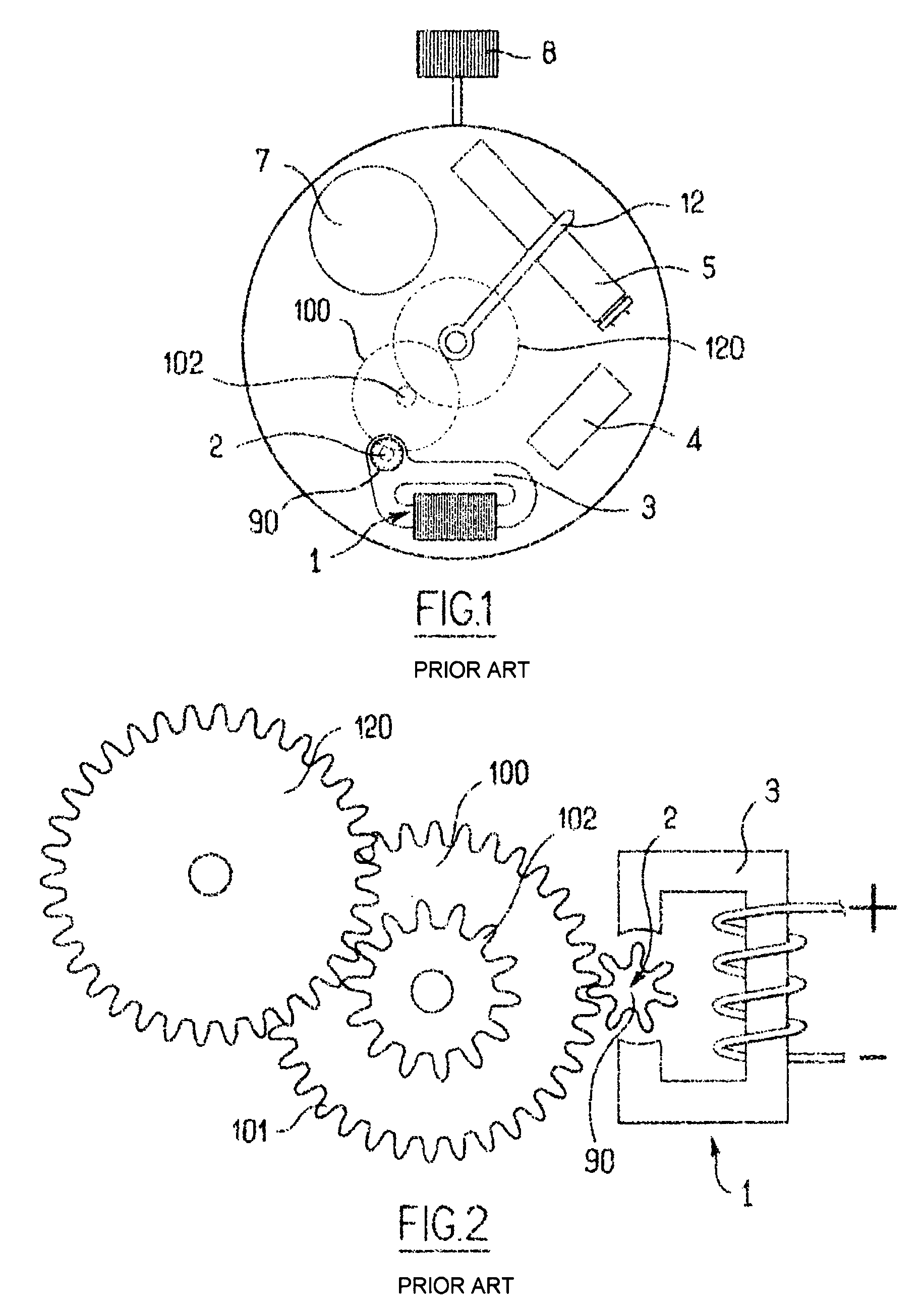
[0050]FIG. 3 represents a quartz watch mechanism according to the invention.

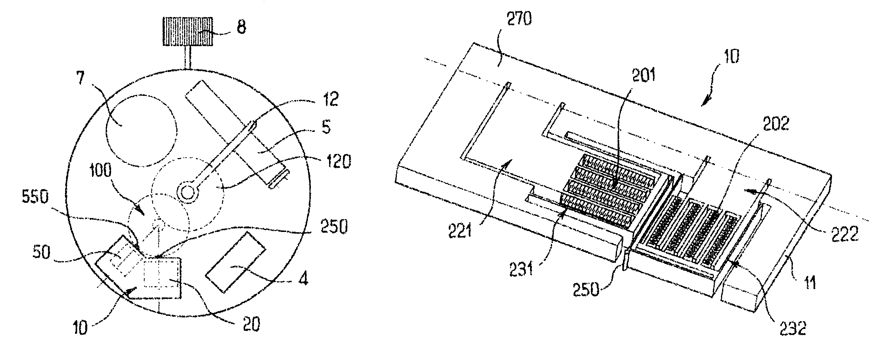
[0051]According to this first embodiment, the watch mechanism is identical to the mechanism shown in FIG. 1, except that the stepping motor and the sprocket wheel 90 have been replaced by a drive device 10 formed by etching a wafer of semiconductor material. The drive device 10 includes a drive element 250 that is capable of meshing sequentially with the driven element 100, and an actuator element 20 that is capable of moving the drive element 250 with a hysteresis-type motion so that it drives a driven element 100 formed by a toothed wheel. The drive element 250 is positioned on an edge of the wafer 11 to allow interfacing with the driven element 100 facing it.

[0052]As can be seen with greater detail in FIGS. 4A and 4B, in the first embodiment, the first gearing stage has been removed in relation to the mechanism of FIG. 1. Through a direct coupling between the drive element 250 and the driven element 100, ...


PUM


Abstract

A drive device formed by etching a wafer. The drive device includes a drive element that can sequentially mesh with a driven element and an actuating element that can displace the drive element according to a hysteresis movement thereby driving the driven element. Placement of the drive element on an outer edge of the wafer enables an interfacing of the drive element with a driven element placed opposite therefrom. A clockwork mechanism including a drive device of the aforementioned type and an input gear that can be rotationally driven by the drive device is also provided.

Description

BACKGROUND OF THE INVENTION[0001]1. Field of the Invention[0002]The invention relates to the area of micro-electromechanical systems (MEMS) or electromechanical microsystems, and more particularly, to the application of these microsystems to clockmaking.[0003]2. Discussion of Related Art[0004]The movements of electromechanical watches or clocks are normally generated by an electric motor such as a micro-motor with a progressive magnetic gap (called a Lavet motor or stepping motor), which drives a series of gear trains in rotation. These watches or clocks require complex gear mechanisms that are used to adapt the movement of the rotor to the various rotation speeds required of the hands.[0005]A concern in the area of clockmaking relates to simplifying the design of the components that constitute the movement generating mechanisms.[0006]Another consideration is reducing the number of components used in the mechanisms. Reducing either or both the number of components and the number of ...

Claims


Application Information

Patent Timeline
Patent Type & Authority Patents(United States)
IPC IPC(8): G04F5/00G04B19/02H02N1/00G04C3/12
CPCG04C3/12
Inventor MINOTTI, PATRICEBOURBON, GILLESLE MOAL, PATRICEJOSEPH, ERIC
Owner SILMACH
Why Eureka
Try Eureka