Heat exchanger and its manufacturing method

a heat exchanger and manufacturing method technology, applied in the direction of lighting and heating apparatus, stationary conduit assemblies, laminated elements, etc., can solve the problems of increasing the cost achieve the effect of improving the reliability of the heat exchanger, providing inexpensively, and easy manufacturing structur

Inactive Publication Date: 2009-12-29
PANASONIC CORP
View PDF10 Cites 8 Cited by
  • Summary
  • Abstract
  • Description
  • Claims
  • Application Information

AI Technical Summary

Benefits of technology

[0009]In the heat exchanger of the present invention, substrates and other substrates are alternately stacked. The former substrates have a plurality of long plates arranged substantially in parallel and slits disposed between the long plates. The latter substrates have a plurality of long plates arranged substantially in parallel, slits disposed between the long plates, and recesses disposed longitudinally continuously in one-side main surfaces of long plates. Thus, about half the total number of substrates requires only simple drilling, so that the structure and manufacturing process of the heat exchanger are simplified.
[0034]The manufacturing method of the heat exchanger of the present invention can provide a heat exchanger that is easy-to-manufacture and has high quality and reliability.

Problems solved by technology

However, for manufacturing the thin circular tubes, a precise processing device is required, and hence the heat exchanger becomes expensive.
Therefore, even when the heat exchanging performance of such a heat exchanger is high, the heat exchanger is extremely expensive, the reliability against the leak of the used fluid is not sufficient, and hence problems remain.

Method used


Image

  • Heat exchanger and its manufacturing method
  • Heat exchanger and its manufacturing method
  • Heat exchanger and its manufacturing method

Examples


first exemplary embodiment

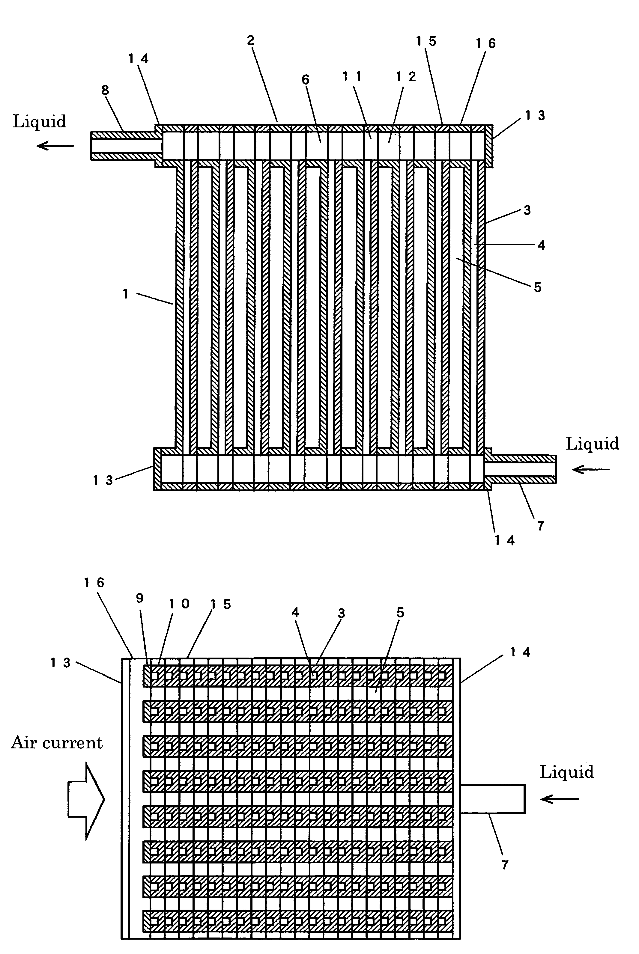
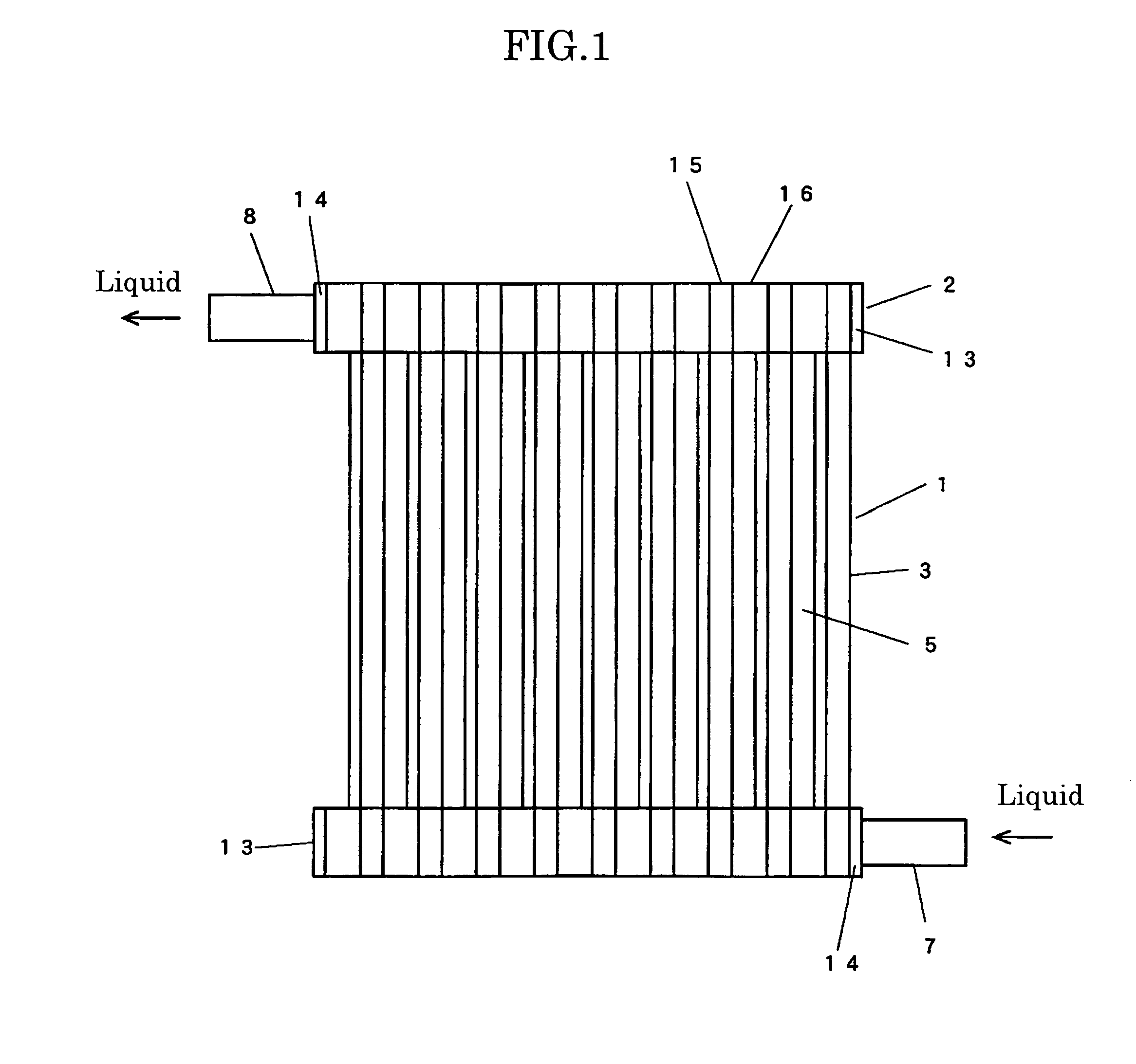
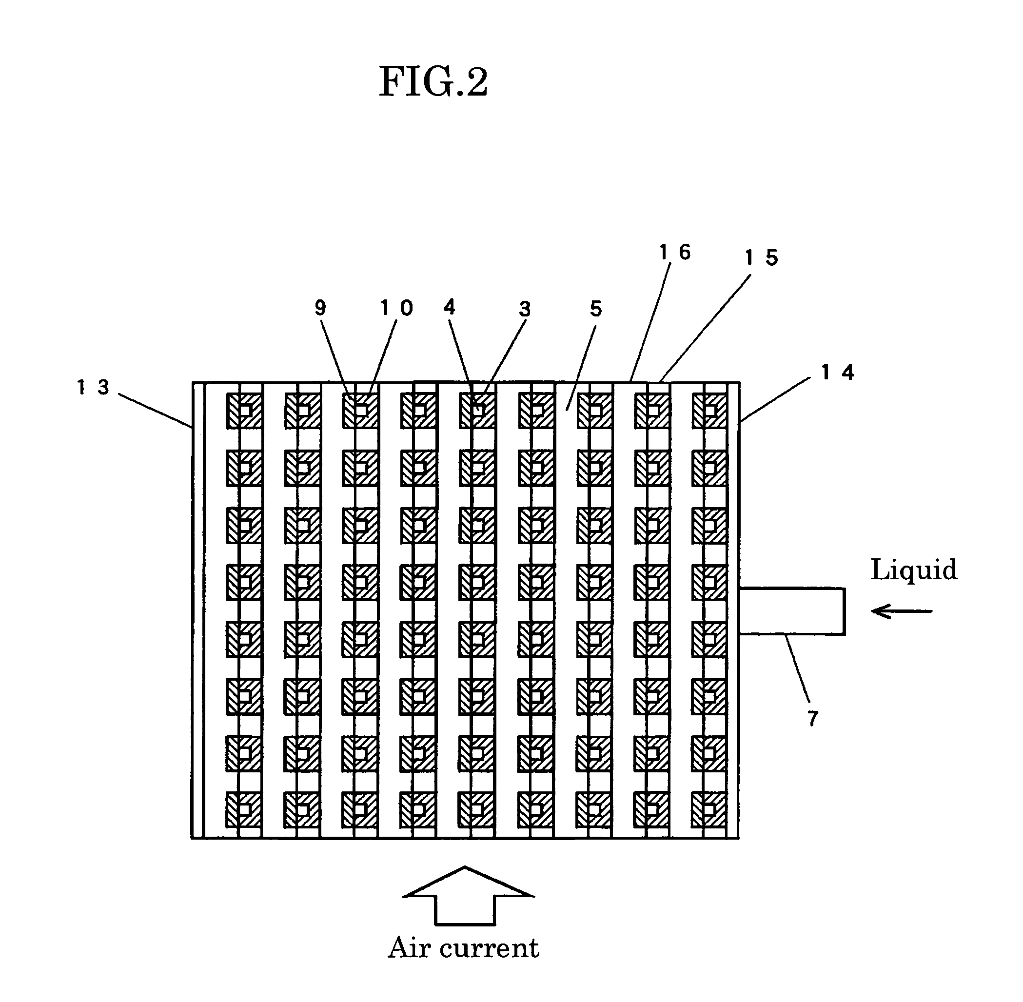
[0104]FIG. 1 is a front view of a heat exchanger in accordance with exemplary embodiment 1 of the present invention. FIG. 2 is a sectional view of a heat exchanging section in the direction orthogonal to the tube axis in the heat exchanger. FIG. 3 is a sectional view of the heat exchanging section in the tube axis direction in the heat exchanger.

[0105]In FIG. 1 through FIG. 3, the heat exchanger has heat exchanging section 1, and header sections 2 disposed at opposite ends of heat exchanging section 1. Heat exchanging section 1 has tubes 3 arranged in a grid shape, tube internal flow channels 4, and tube external flow channels 5. Header sections 2 include branch flow channels 6, inflow tube 7, and outflow tube 8. Tube internal flow channels 4 are connected to branch flow channels 6. Each tube 3 has a substantially square cross section, and has band-like long plate 9 and long plate 10 having U-shaped cross section. Each branch flow channel 6 is formed by continuously interconnecting ...

second exemplary embodiment

[0119]FIG. 11 is a perspective view of a heat exchanging section in accordance with exemplary embodiment 2 of the present invention.

[0120]FIG. 12 is a front view of a first substrate in accordance with exemplary embodiment 2. FIG. 13 is a front view of a second substrate in accordance with exemplary embodiment 2. The heat exchanging section is formed by alternately stacking first substrates 26 and second substrates 28. A plurality of first slits 30 and a plurality of second slits 40 are alternately arranged substantially in parallel on each first substrate 26. Third slits 50 having the same shape as that of first slits 30 are disposed on each second substrate 28 at the same positions as the projection positions of first slits 30.

[0121]First slits 30 and third slits 50 overlap each other on the projection plane and communicate with each other, thereby forming tube external flow channels 60. The longitudinal size of third slits 50 disposed on second substrate 28 is shorter than that o...

third exemplary embodiment

[0133]FIG. 19 is a perspective view of a heat exchanging section in accordance with exemplary embodiment 3 of the present invention. The heat exchanging section is formed by stacking first substrates 126 and second substrates 128 so that first substrates 126 are sandwiched between second substrates 128. First slits 130 and third slits 150 form tube external flow channels 160 similarly to embodiment 2. Second slits 140 and second substrates 128 form tube internal flow channels 170. Three first substrates 126 are stacked between second substrates 128 on the inflow side of the external fluid, two first substrates 126 are stacked between them in the intermediate part, and one first substrate 126 is disposed between them on the outflow side thereof. Thus, tube internal flow channels 170 are enlarged in the substrate stacking direction on the inflow side of the external fluid.

[0134]Three rows of first substrates 126 are disposed in the flow direction of the external fluid in embodiment 3;...


PUM

PropertyMeasurementUnit
outer diameteraaaaaaaaaa

Abstract

A heat exchanger which, while having excellent heat exchanging performance, has a structure easy to produce, is of low cost, and has high quality and reliability. The heat exchanger has first base plates (26), in each of which first slits (30) and second slits (40) are provided in substantially parallel to each other, and has second base plates (28), in each of which third slits (50) with substantially the same shape as a first slit (30) are provided. The length in the longitudinal direction of a second base plate (28) is set to be less than the length of a second slit (40). The first base plates (26) and the second base plates (28) are layered over each other such that the first slits (30) provided in the first base plates (26) and the third slits (50) provided in the second base plates (28) are communicated. Flow paths (60) outside tubes are constructed by the first slits (30) provided in the first base plates (26) and the third base plates (50) provided in the second base plates (28). Flow paths (70) inside the tubes are constructed by the second slits (40) provided in the first base plates (26) and the second base plates (28). Since a heat exchanging section formed only by tubes can be constructed by the base plates with the slits, the heat exchanger can be easily produced. Further, the heat exchanger can be provided at low cost.

Description

RELATED APPLICATIONS[0001]This application is the U.S. National Phase under 35 U.S.C. §371 of International Application No. PCT / JP2005 / 007062 filed on Apr. 12, 2005, which in turn claims the benefit of Japanese Application No. 2004-118621 filed on Apr. 14, 2004, and Japanese Application No. 2005-035624 filed on Feb. 14, 2005, the disclosures of which Applications are incorporated by reference herein.TECHNICAL FIELD[0002]The present invention relates to a heat exchanger for a cooling system, a heat radiation system, and a heating system, and more particularly to a heat exchanger of liquid and gas used in a system such as an information device requiring compactness.BACKGROUND ART[0003]Conventionally, a heat exchanger formed of tubes and fins is generally used. For aiming at compactness, recently, the tube diameter and tube pitch have been decreased, and the tube density has been increased. For example, a heat exchanging section is formed of extremely thin tubes of which outer diameter...

Claims


Application Information

Patent Timeline
Patent Type & Authority Patents(United States)
IPC IPC(8): F28D1/03F28D1/053F28F3/08
CPCF28F3/086Y10T29/4935
Inventor TANIGUCHI, MITSUNORIKIDO, OSAOMAMEMOTO, TOSHIAKI
Owner PANASONIC CORP
Why Eureka
Try Eureka