
Compact optical see-through head-mounted display with occlusion support

a head-mounted display and compact technology, applied in the field of head-mounted displays, can solve problems such as occlusion problems, lag due, and problems such as augmented reality seethrough and other problems

Inactive Publication Date: 2009-12-29
UNIV OF CENT FLORIDA RES FOUND INC
View PDF8 Cites 192 Cited by
  • Summary
  • Abstract
  • Description
  • Claims
  • Application Information

AI Technical Summary

Benefits of technology

"The present invention provides methods, apparatus, and systems for compact optical see-through head worn displays with occlusion support. The invention allows virtual objects to occlude real objects and provides a spatial light modulator that allows viewers to block or pass certain parts of a scene. The invention also includes a novel optical display system with a lens, polarizer, prism, and reflective spatial light modulator for producing a modulated output. The technical effects of the invention include mutual occlusions, which provide a strong desired attribute for certain applications, and a display that is useful for virtual objects able to occlude real objects."

Problems solved by technology

From a human usability point of view, there are several issues with video see-through augmented reality such as lag due to processing of the incoming video stream in video see through augmented reality is a problem.
However, regardless of the transmission / reflection percentages, some light is always transmitted from the scene under various non-zero illumination settings, which is the source of the occlusion problem.
This transmitted light implies that with only a beam-splitter and an image source based display, it is optically challenging to create mutual occlusion of real and computer-generated objects.
Current computer graphics techniques and hardware allow for “hidden line removal” or visible surface determination, however, the display of computer-generated “opaque” objects with optical see-through remains a problem.

Method used


Image

  • Compact optical see-through head-mounted display with occlusion support
  • Compact optical see-through head-mounted display with occlusion support
  • Compact optical see-through head-mounted display with occlusion support

Examples


Embodiment Construction

[0032]Before explaining the disclosed embodiments of the present invention in detail it is to be understood that the invention is not limited in its applications to the details of the particular arrangements shown since the invention is capable of other embodiments. Also, the terminology used herein is for the purpose of description and not of limitation.

[0033]The following is a list of the reference numbers used in the drawings and the detailed specification to identify components.

[0034]

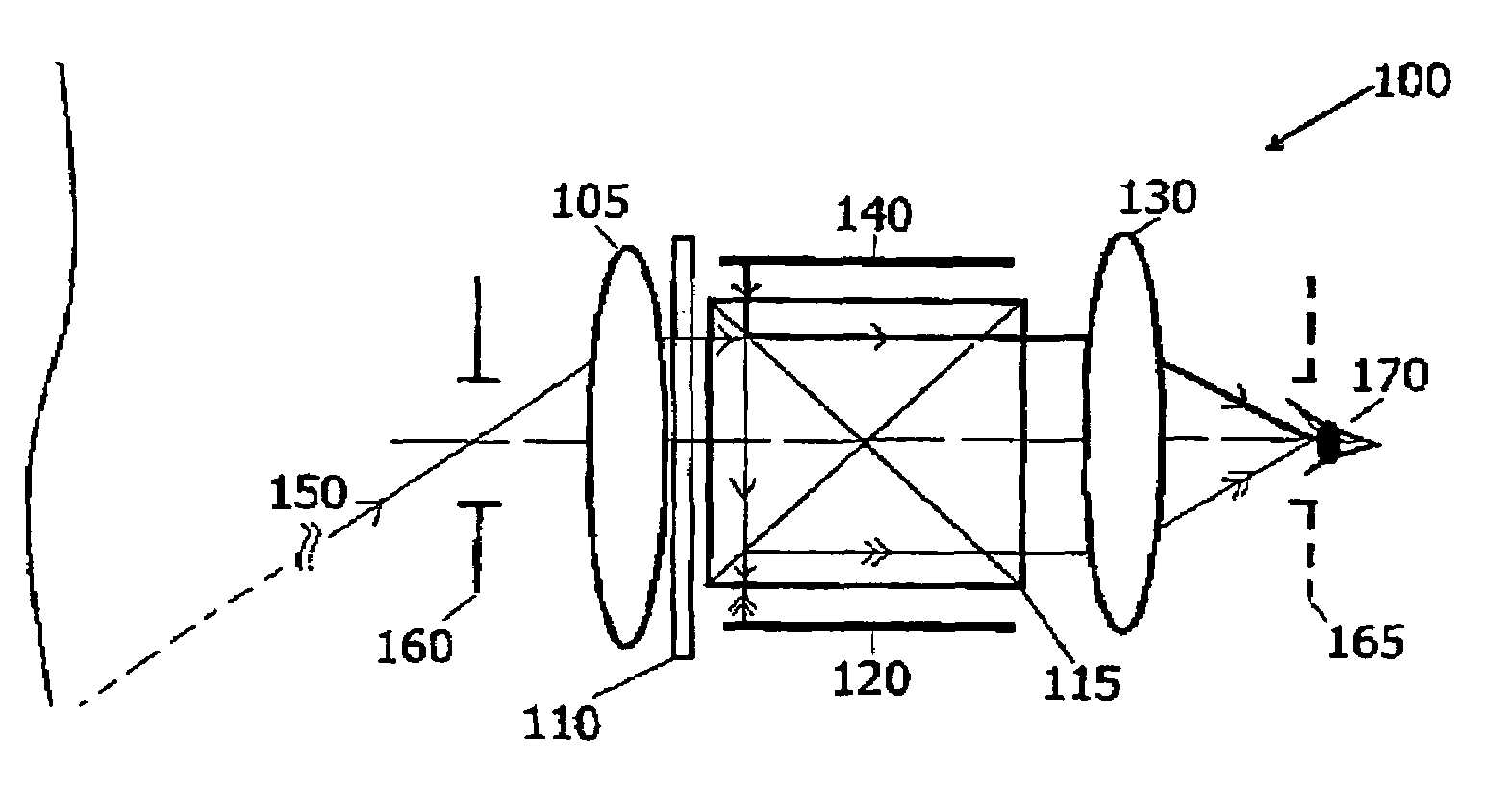
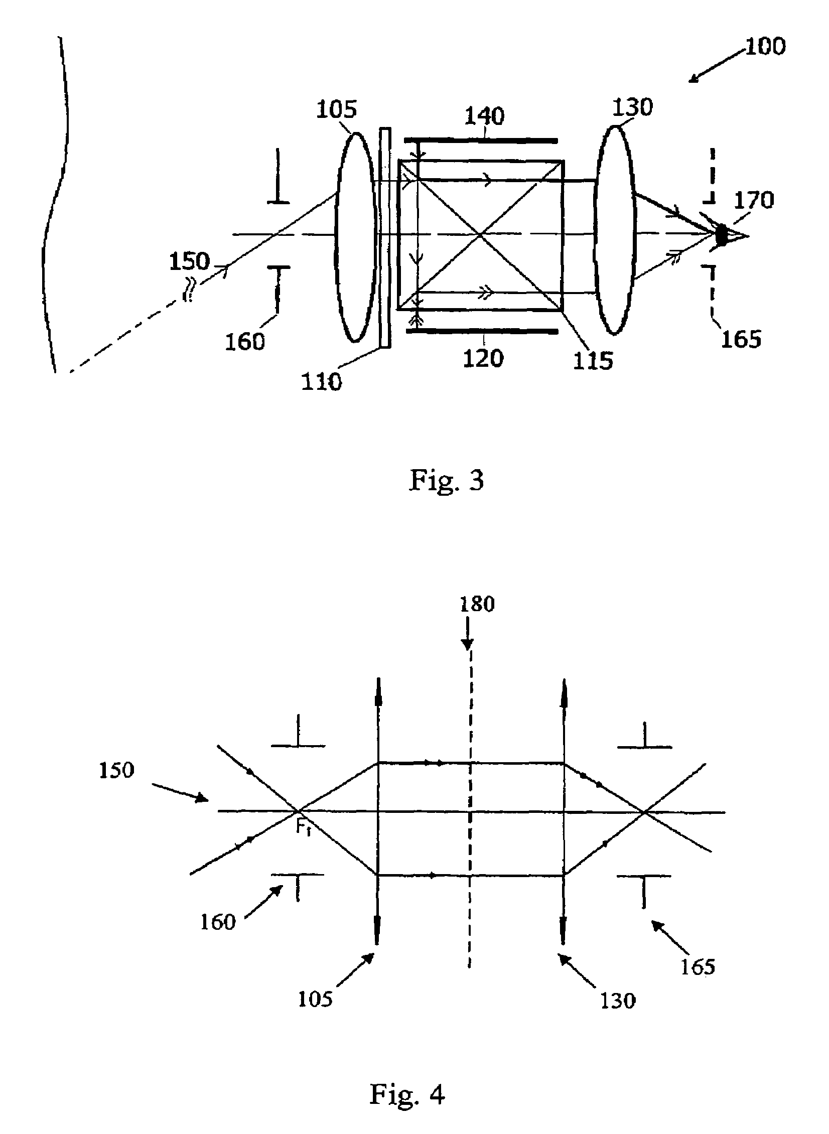
100optical system105objective lens110polarizer115x-cube prism120spatial light modulator130eyepiece140micro display / LCD150chief rays160entrance pupil165exit pupil170eye180intermediary image plane190Scene900test fixture905light source910diffuser sheet915transparency920first lens925polarizing beam splitter930liquid crystal optical shutter940F-LCOS / LCD945second lens950driver

[0035]Depending on the optical properties of a material, light is either transmitted through the material, reflected, or it is abso...


PUM


Abstract

An optical system, apparatus and method are capable of mutual occlusions. The core of the system is a spatial light modulator (SLM) which allows users to block or pass certain parts of a scene which is viewed through the head worn display. An objective lens images the scene onto the SLM and the modulated image is mapped back to the original scene via an eyepiece. The invention combines computer-generated imagery with the modulated version of the scene to form the final image a user would see. The invention is a breakthrough in display hardware from a mobility (i.e. compactness), resolution, and speed, and is specifically, related to virtual objects being able to occlude real objects and real objects being able to occlude virtual objects.

Description

[0001]This application claims the benefit of priority from U.S. provisional patent application Ser. No. 60 / 573,529, filed on May 21, 2004 and was funded by the Office of Naval Research grant N00014-03-10667.FIELD OF THE INVENTION[0002]This invention relates to head-mounted displays, and in particular, to optical see-through head worn display systems, apparatus and methods that are capable of mutual occlusions, wherein virtual objects are able to occlude real objects and real objects are able to occlude virtual objects.BACKGROUND AND PRIOR ART[0003]Augmented reality can be defined as adding or subtracting information to the human senses. Visual augmentations can be superimposed with a head-worn display Head-Worn Displays allow full mobility and private access to information. Head worn displays can be classified into two classes, optical and video see-through as described by Rolland and Fuchs, Optical versus video see-through head mounted displays in medical visualization, Presence Vo...

Claims


Application Information

Patent Timeline
Patent Type & Authority Patents(United States)
IPC IPC(8): G09G5/00
CPCG02B27/0172G02B27/1066G09G3/002G02B27/149G02B5/30G09G2340/12G02B2027/0118
Inventor HA, YONGGANGROLLAND, JANNICKCAKMAKCI, OZAN
Owner UNIV OF CENT FLORIDA RES FOUND INC
Learn More