
Ammonia storage for on-vehicle engine

a technology for ammonia storage and on-board vehicles, which is applied in the direction of machines/engines, iron sulfates, separation processes, etc., can solve the problems of difficult to safely store hydrogen gas on-board vehicles, and achieve the effect of efficient and reversible processes

Inactive Publication Date: 2010-01-05
GM GLOBAL TECH OPERATIONS LLC
View PDF7 Cites 8 Cited by
  • Summary
  • Abstract
  • Description
  • Claims
  • Application Information

AI Technical Summary

Benefits of technology

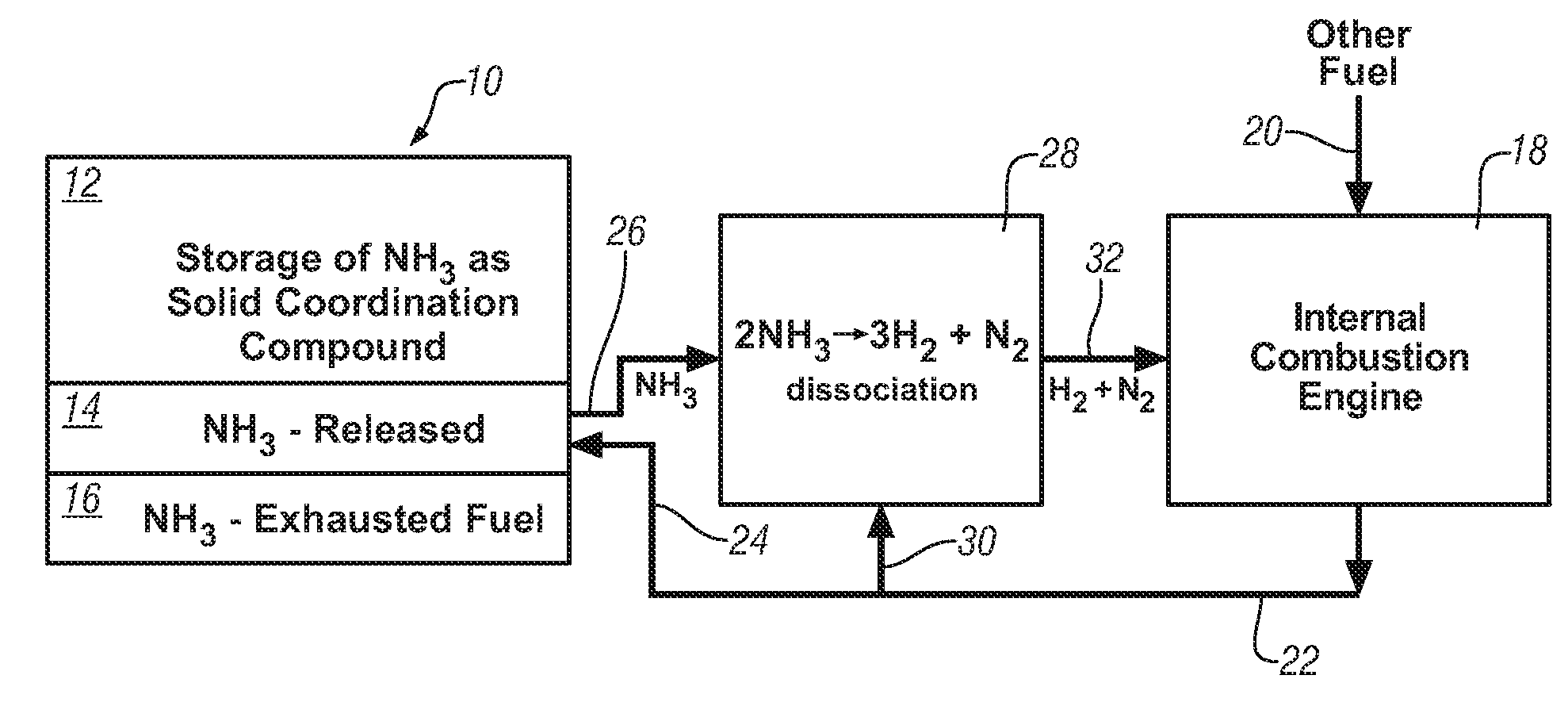
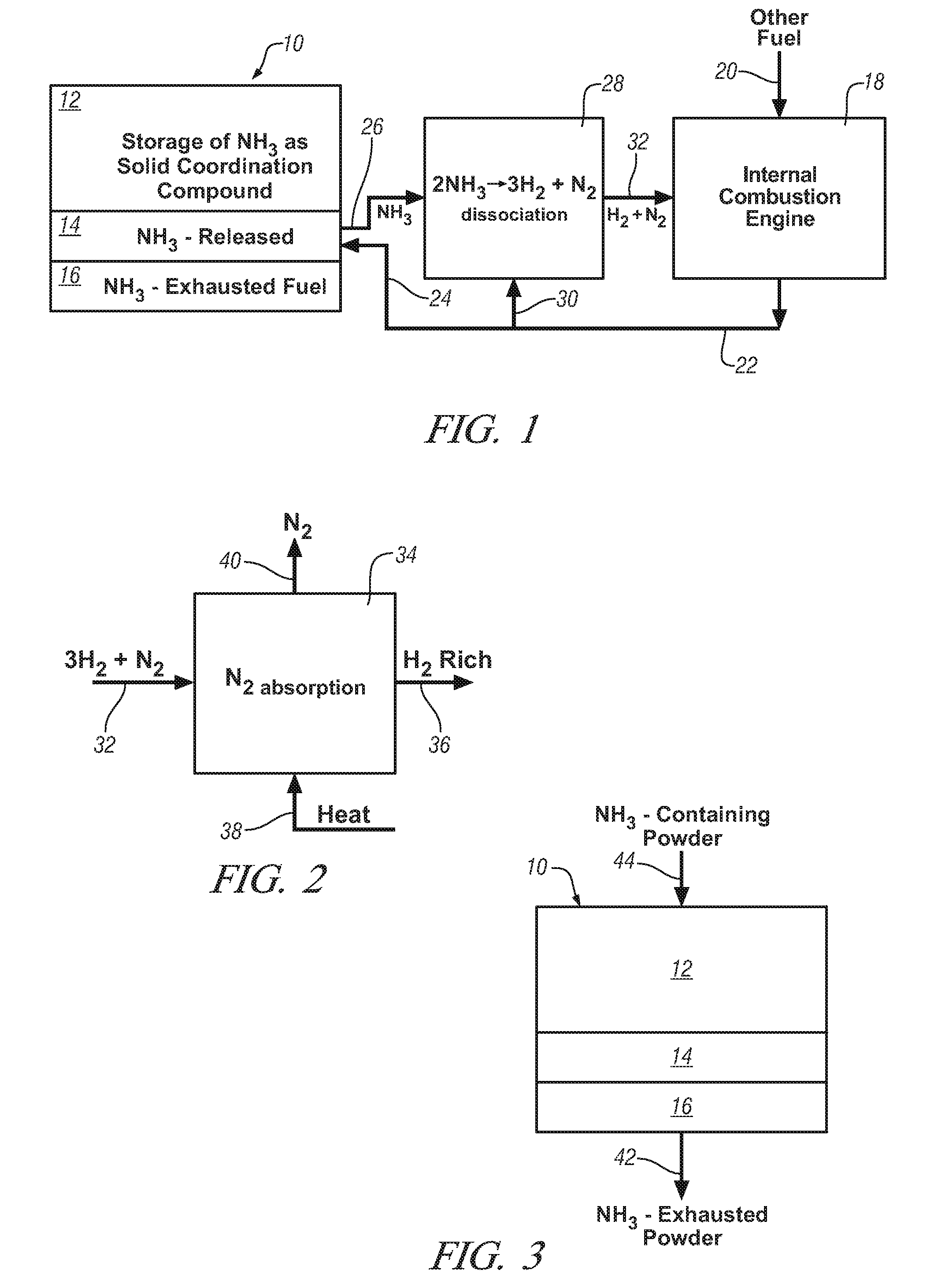
The patent describes a method for storing and using ammonia as a fuel precursor in vehicles. Ammonia is stored as a solid composition with a transition metal compound, which releases ammonia when heated. The ammonia is then decomposed into hydrogen and nitrogen using a catalyst, and the hydrogen is used as a fuel in the vehicle engine. The ammonia can be reacted with ammonia to restore its content and used again. The use of ammonia as a fuel precursor can be adapted to different driving conditions. The technical effect of this patent is to provide a reliable and efficient way to store and use ammonia as a fuel in vehicles.

Problems solved by technology

There is also interest in supplementing gasoline with hydrogen but it is difficult to safely store hydrogen gas on-board a vehicle.

Method used


Image

  • Ammonia storage for on-vehicle engine
  • Ammonia storage for on-vehicle engine

Examples


experimental examples

[0030]The following examples illustrate the absorption of ammonia as a ligand into various metal compounds and the subsequent release of ammonia from the respective compounds.

example 1

[0031]5 grams of ferrous (F+2) sulfate was ground to fine powder of close to one micron particle size and placed in a glass tube flow-through reactor. The powder was exposed to flow of ammonia gas (600 ml / min) for one hour. The weight of the powder increased during the exposure to ammonia and the sample was determined as having absorbed close to six ammonia molecules per formula unit (e.g., FeII(NH3)about 6SO4). The sample was saturated with ammonia in less than 30 minutes. One hundred milligrams of the sample was placed in a thermogravimetric analyzer and heated at 5 degrees per minutes under flow of argon gas. The sample weight was reduced in two steps and at 250° C. the ferrous sulfate sample released close to 5.5 mole ammonia per formula unit.

[0032]Four grams of the sample saturated with ammonia in this example, was placed in a flow-through glass tube reactor and heat treated at 250° C. under flow of argon. The sample was weighed after 30 minutes heat treatment. The sample weigh...

example 2

[0034]Five grams of hydrated ferrous sulfate was placed in a glass tube reactor. The sample was heat treated under argon gas to 250° C. for 30 minutes to remove the water of crystallization. The dehydrated sample was cooled to room temperature and exposed to flowing stream of ammonia for 30 minutes. The sample weight was measured. The sample absorbed close to six ammonia molecules per formula weight of ferrous sulfate. The absorbed ammonia was then released by switching the ammonia gas to argon gas and heat treating the sample to 250° C. and marinating the heat for 30 minutes. The ammonia absorption and removal processes were repeated four times. It is observed that dehydrated iron sulfate absorbs and releases ammonia gas at a faster rate than was obtained with the anhydrous ferrous sulfate sample. Also, the color change of the ferrous sulfate powder, from light blue to dark blue as ammonia was absorbed and from dark blue to light blue as ammonia is released, occurred much faster th...


PUM


Abstract

Ammonia is used as precursor source of hydrogen fuel in an on-vehicle internal combustion engine. Ammonia is stored as, for example, a ligand in an on-vehicle transition metal composition. Upon demand for hydrogen by the vehicle's engine control system, ammonia is expelled as a gas from some of the composition and the ammonia gas is dissociated into a mixture of hydrogen and nitrogen and delivered as a fuel-containing mixture to the engine. In a preferred embodiment, the hydrogen is used as a supplement to gasoline as a fuel for engine operation.

Description

TECHNICAL FIELD[0001]This disclosure pertains to the reversible storage of ammonia in a solid compound as a hydrogen precursor fuel source for an on-vehicle internal combustion engine adapted to operate on hydrogen or, for example, a combination of hydrogen and gasoline as fuel. For example, ammonia is stored as a ligand in a transition metal coordination compound, and, when hydrogen is required, ammonia is released from the compound, dissociated into hydrogen and nitrogen, and the hydrogen-nitrogen mixture delivered to the engine for combustion of its hydrogen content. Alternatively, a separation of the hydrogen and nitrogen may be performed and hydrogen delivered as a hydrogen-rich stream for combustion.BACKGROUND OF THE INVENTION[0002]There is interest in reducing consumption of gasoline in vehicles powered by internal combustion engines. To achieve this goal, some vehicle engine systems are adapted to recognize and distinguish between gasoline or a mixture of gasoline and ethano...

Claims


Application Information

Patent Timeline
Patent Type & Authority Patents(United States)
IPC IPC(8): F02B43/08
CPCC01B3/047C01C1/006C01G49/14C01G51/10C01G51/12C01G53/10C01G53/12Y02E60/364Y02E60/36Y10S123/12
Inventor NAZRI, GHOLAM-ABBAS
Owner GM GLOBAL TECH OPERATIONS LLC
Learn More