
Seedbed conditioning vertical tillage apparatus

a technology of vertical tillage and seedbed, which is applied in the direction of clod crushing, agricultural tools and machines, agricultural machines, etc., can solve the problems of affecting the tillage effect, and the backside of the disk tends to smear and compress soil,

Active Publication Date: 2010-01-05
BLUE LEAF I P INC
View PDF45 Cites 7 Cited by
  • Summary
  • Abstract
  • Description
  • Claims
  • Application Information

AI Technical Summary

Benefits of technology

The patent describes an apparatus for soil conditioning for transport through a field in an advancing direction. The apparatus includes a frame, a rotary harrow, and a plurality of disks. The disks are arranged in front of the rotary harrow and are angled between 7 and 10 degrees with respect to the frame axis. Each disk includes a scalloped peripheral edge with a plurality of teeth, and a space between each tooth. The apparatus is designed to engage soil below the frame and improve soil quality for agricultural purposes. The technical effects of the invention include improved soil conditioning, reduced soil compaction, and increased soil penetration by the rotary harrow.

Problems solved by technology

Unfortunately, while these types of tilling tools loosen or till top soil well, these types of tools tend to compact under soil (i.e., soil below the top soil) as portions of the soil engaging components smear across the under soil during travel.
More specifically, when a deep dish disk is inclined relatively steeply to a travel direction, the backside of the disk tends to smear and compress soil therebelow.
Here, the spikes of each toothed member penetrate soil by being driven substantially vertically downward and disrupt the soil as the spike angle within the soil changes during member rotation.
While rotary spike harrows reduce smearing / soil compaction, unfortunately these types of tilling tools have several shortcomings.
First, rotary spike toothed harrows usually include a relatively large number of toothed members arranged on an axle so that the weight of the tilling implement is distributed over a large number of member teeth and the spikes do not, under typical soil conditions, penetrate the soil being tilled to a desired level during a single pass.
Second, rotary spike toothed harrows do not level soil to the same extent as other types of tilling tools during a single pass through a field.
Obviously additional passes require additional time and thus are not desirable.

Method used


Image

  • Seedbed conditioning vertical tillage apparatus
  • Seedbed conditioning vertical tillage apparatus
  • Seedbed conditioning vertical tillage apparatus

Examples


Embodiment Construction

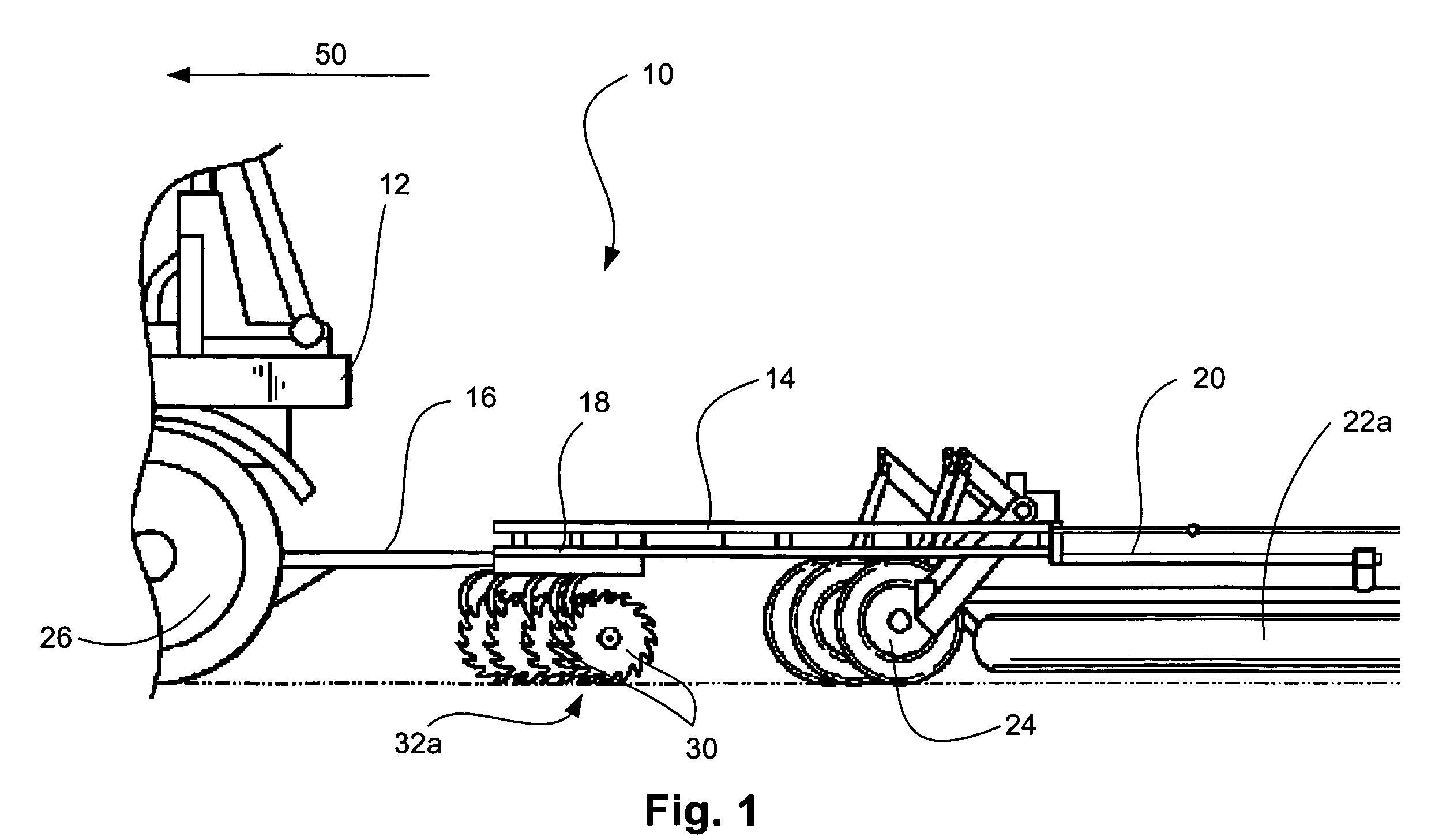
[0025]Referring now to the drawings wherein like reference numerals correspond to similar elements throughout the several view and, more specifically, referring to FIG. 1, the present invention will be described in the context of an exemplary work vehicle 12 having a vehicle support structure to which a plurality of wheels 26 are rotatably mounted. A work vehicle 12 typically has a power source coupled to a transmission with the transmission operatively coupled to at least two of the wheels 26. The power source can be an internal combustion engine such as a gasoline engine or a diesel engine and it may also be an electric motor or a steam driven turbine.

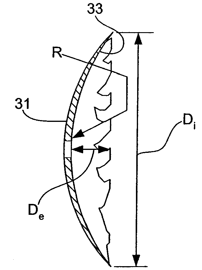
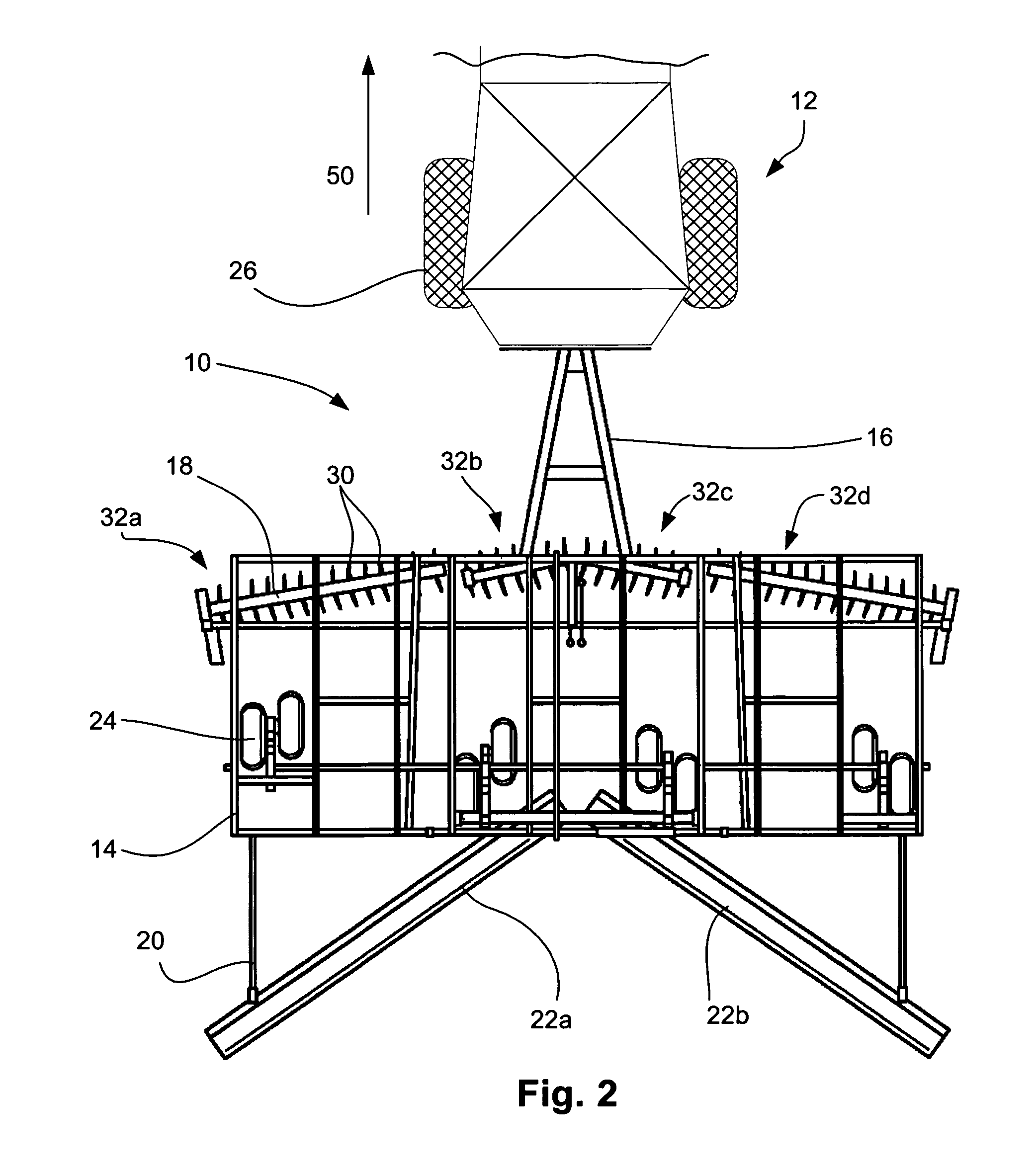
[0026]Referring still to FIG. 1 and also to FIG. 2, a tillage assembly 10 is illustrated which is linked to tractor 12 by a tow bar 16. In addition to tow bar 16, tillage assembly 10 includes a main frame 14, wheels, one subassembly of wheels identified by numeral 24, first through forth disk subassemblies 32a, 32b, 32c and 32d and f...


PUM


Abstract

A method and apparatus for soil conditioning, the apparatus comprising a frame, a rotary harrow supported by the frame for engaging the soil and a plurality of disks supported by the frame and in front of the rotary harrow along the advancing direction for rotation about disk axis and for engaging soil below the frame, each disk including a scalloped peripheral edge that forms a plurality of teeth and a space between each two adjacent teeth.

Description

CROSS-REFERENCE TO RELATED APPLICATIONS[0001]Not applicable.STATEMENT REGARDING FEDERALLY SPONSORED RESEARCH OR DEVELOPMENT[0002]Not applicable.BACKGROUND OF THE INVENTION[0003]The present invention is related to seedbed conditioning tillage tools and more specifically to vertical tillage tools.[0004]To prepare a seed bed for planting, many types of tilling tools have been developed. Currently, the most commonly used tilling tools include cultivators and combination tillage units that include soil engaging components (i.e., disks, tillage tines, etc.) that completely sweep (i.e., smears) an entire tillage floor to turn over and loosen all of the top soil that covers a field. For example, some tillage systems may include two rows of disks arranged such that the disks essentially completely turn over all top soil in a field. To this end, the disks are designed to have characteristics and are juxtaposed with respect to each other and a travel direction such that all of the soil is turn...

Claims


Application Information

Patent Timeline
Patent Type & Authority Patents(United States)
IPC IPC(8): A01B5/00
CPCA01B7/00A01B27/005
Inventor KNOBLOCH, DEAN A.
Owner BLUE LEAF I P INC
Learn More