Flow turning vane assembly with integrated hydrocarbon adsorbent

a technology of hydrocarbon adsorbent and flow turning vanes, which is applied in the direction of machine/engine, combustion-air/fuel-air treatment, and separation processes, etc., can solve the problems of low adsorption efficiency, low adsorption efficiency, and pressure loss, and achieve low flow restriction (pressure loss), enhance flow performance, and high hydrocarbon trapping capacity

Inactive Publication Date: 2010-01-05
GM GLOBAL TECH OPERATIONS LLC
View PDF10 Cites 19 Cited by
  • Summary
  • Abstract
  • Description
  • Claims
  • Application Information

AI Technical Summary

Benefits of technology

[0011]An advantage of an embodiment is that the flow turning vane assembly can provide high hydrocarbon trapping capacity during engine shutdown, with low flow restriction (pressure loss) around a bend in a clean air duct during engine operation. Thus, the device functions to simultaneously enhance flow performance and reduce hydrocarbon emission from the air induction system.
[0012]An advantage of an embodiment is that the flow turning vane assembly is compact and cost effective since it provides an integrated unit which serves both purposes of providing flow turning and hydrocarbon adsorbing capability. The assembly may also save cost by providing both functions with less manufacturing assembly steps. The assembly is compact, helping with vehicle component packaging, since it is in the duct and does not take up extra engine compartment space.
[0013]An advantage of an embodiment is that the flow turning vane assembly can be located at the duct bend section, where the assembly may have the most benefit—higher adsorbing efficiency and lower pressure loss.

Problems solved by technology

However, the emissions and fuel economy requirements are creating the undesired effect of causing more flow restrictions.
A concern with this type of trapping device is that it may have a relatively low adsorbing efficiency, with only a small amount of hydrocarbon molecules being trapped relative to the size of the trap.
While this type of hydrocarbon adsorbent generally has higher adsorbing efficiency, it creates a restriction in the air flow path, thereby causing pressure loss.
But this, then, results in the low adsorbing efficiency that was inherent in the non-flow-through types.
The other type of vehicle requirement—fuel economy—may also lead to air flow restrictions, although indirectly so.
This reduction in size often leads to packaging compromises that require the shape of the air induction system components to be less than ideal for maximum air flow.
The 90-degree bend of the clean air duct causes significant flow recirculation and stagnant flow near the inside of the bend, with a resulting air flow pressure loss in this duct.
The air flow pressure loss can lead to a reduction in the maximum engine power output.
But turning vanes are not commonly used in air induction system because they are typically not cost effective if used only for reducing the pressure loss.
In many cases, engineers cannot justify the benefits of turning vanes compared to the cost associated with adding the vanes.
So instead, engineers struggle with increasing bend ratios (bend radius / duct diameter) as much as possible.
However, due to packaging constraints in the vehicle engine compartment, engineers often come up short of the desired bend ratio and live with the pressure loss caused by the sharp bend in the clean air duct.

Method used


Image

  • Flow turning vane assembly with integrated hydrocarbon adsorbent
  • Flow turning vane assembly with integrated hydrocarbon adsorbent
  • Flow turning vane assembly with integrated hydrocarbon adsorbent

Examples


Embodiment Construction

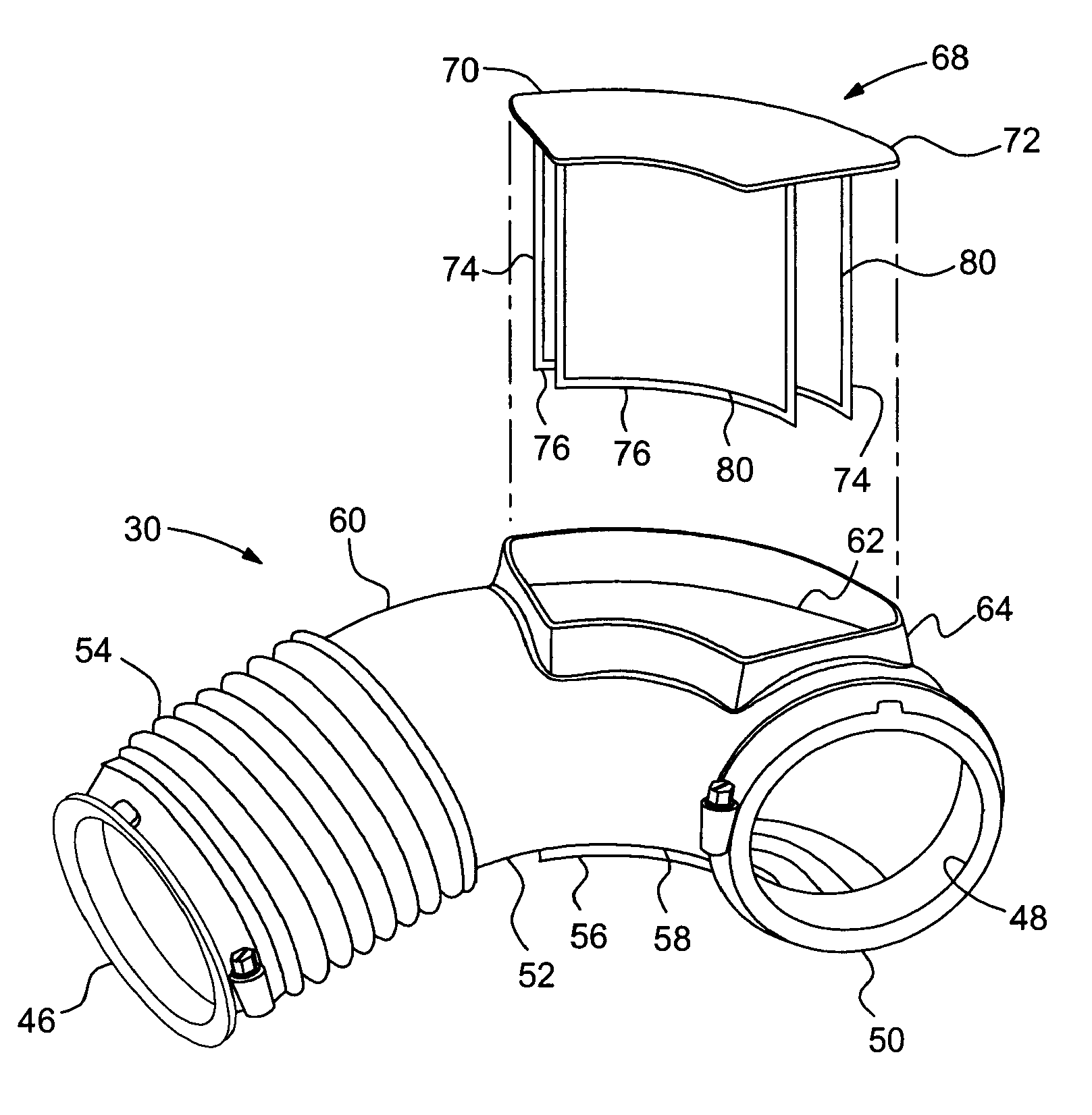
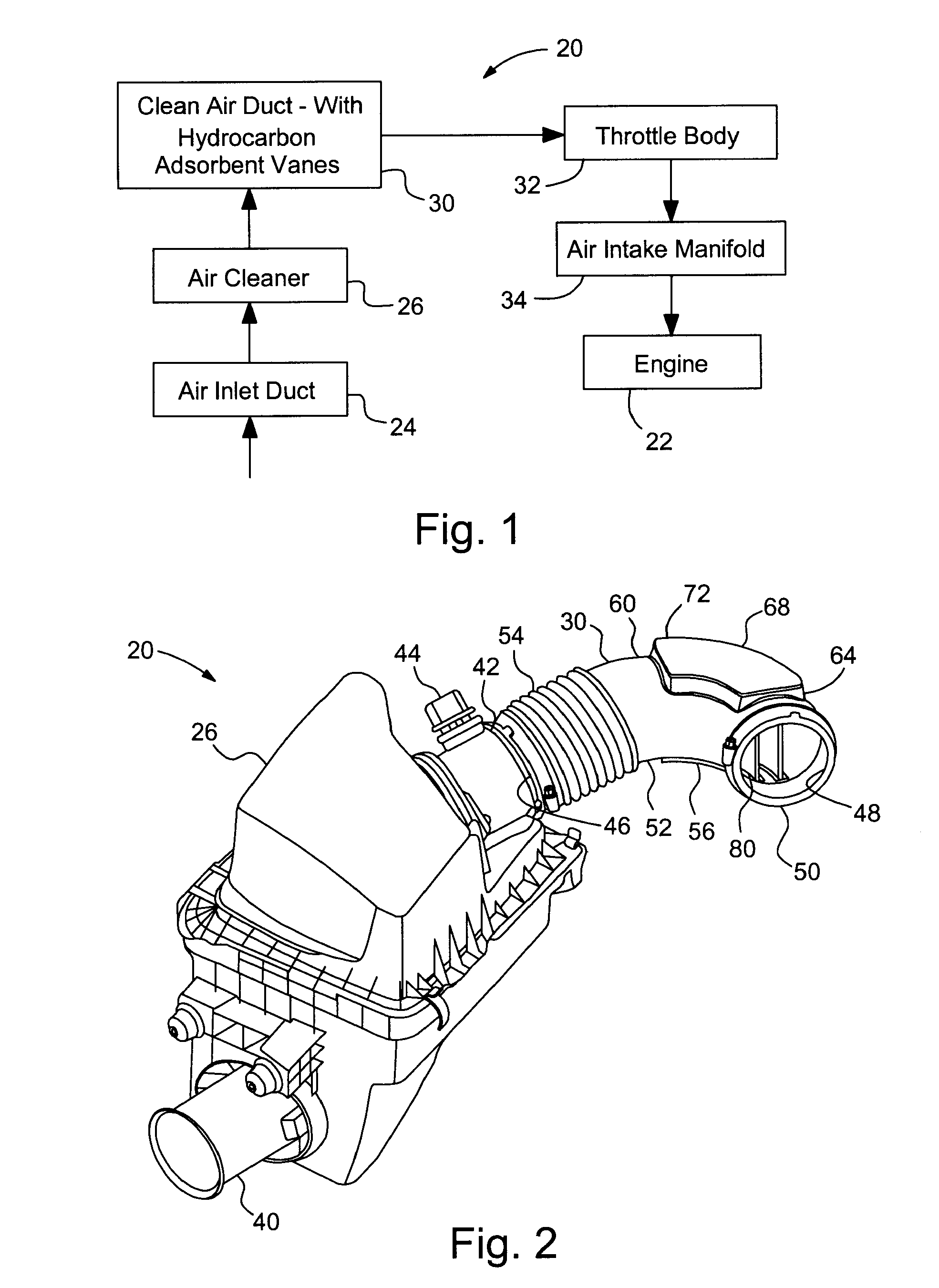
[0024]FIG. 1 shows a block diagram of an air induction system 20 directing air to a vehicle engine 22. The air induction system 20 includes an inlet duct 24 that opens to the atmosphere and directs flow into an air cleaner 26, where the air is filtered. A clean air duct 30 is in fluid communication with an outlet of the air cleaner 26. The clean air duct 30 includes a flow turning vane assembly with hydrocarbon adsorbent vanes, which will be discussed in more detail below. The clean air duct directs air to a throttle body 32 (either directly or through another duct). The throttle body 32 is in fluid communication with an air intake manifold 34. The air intake manifold 34, in turn, directs the air to intake valves (not shown) of the engine 22.

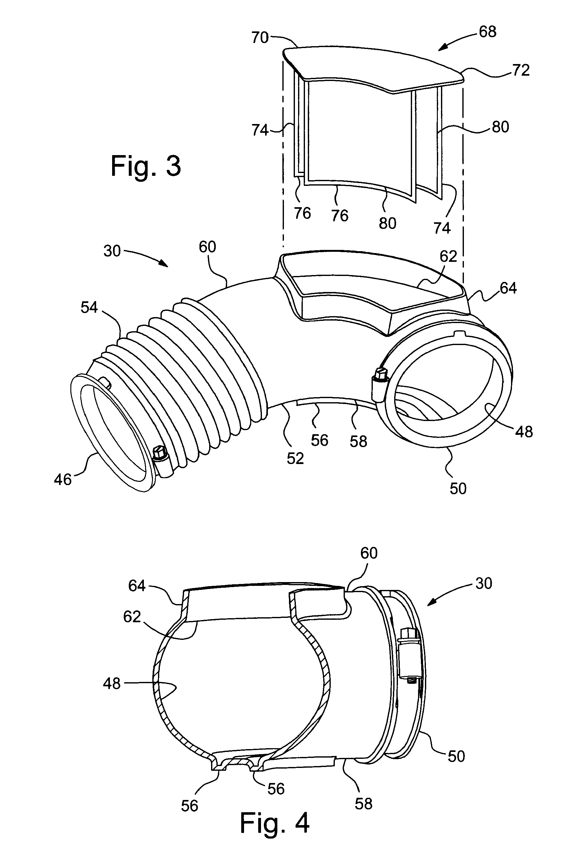
[0025]FIGS. 2-5 illustrate a portion of the air induction system 20 of FIG. 1 in more detail, according to a first embodiment. An inlet 40 directs air into the air cleaner 26, with the air flowing through an air filter (not shown) before flowing...


PUM

PropertyMeasurementUnit
perimeteraaaaaaaaaa
flexibleaaaaaaaaaa
sizeaaaaaaaaaa

Abstract

The invention concerns a flow turning vane assembly for use in a duct bend portion of a clean air duct of an air induction system for a vehicle engine. The flow turning vane assembly may have a vane support housing, and a hydrocarbon adsorbent vane mounted to the vane support housing. The hydrocarbon adsorbent vane has a curved shape complimentary to the duct bend portion and includes a hydrocarbon adsorbent layer.

Description

BACKGROUND OF THE INVENTION[0001]The present invention relates generally to an air induction system for a vehicle engine and more particularly to flow turning vanes and hydrocarbon adsorbents included in the air induction system.[0002]Motor vehicle manufacturers are continually trying to obtain greater power output from given size engines, even while meeting new environmental emissions and fuel economy requirements. One area of the overall engine system that is being closely scrutinized is the air induction system. This area is being scrutinized because one factor relating to the maximum engine power output is the air flow capacity through the air induction system—the lower the air flow capacity the lower the maximum engine power output. Consequently, the pressure loss of the air induction system must be minimized to provide a desired amount of air flow for maximizing engine power output. However, the emissions and fuel economy requirements are creating the undesired effect of causi...

Claims


Application Information

Patent Timeline
Patent Type & Authority Patents(United States)
IPC IPC(8): B03C3/41
CPCF02M35/024F02M35/10019F02M35/10144F02M35/10262F02M35/10386F02M25/08F02M35/02F02M35/10137Y02T10/146Y10S95/901Y02T10/12
Inventor LI, LEI
Owner GM GLOBAL TECH OPERATIONS LLC
Why Eureka
Try Eureka