Collector for solar radiation

a solar energy and collector technology, applied in the direction of light radiation electric generators, generators/motors, lighting and heating apparatus, etc., can solve the problems of increasing the cost of solar energy conversion, and increasing the complexity of the concentrator structure, so as to achieve simple lateral buoyancy balance, and the effect of increasing the energy per unit area

Inactive Publication Date: 2010-01-05
SUNENGY PTY LTD
View PDF15 Cites 24 Cited by
  • Summary
  • Abstract
  • Description
  • Claims
  • Application Information

AI Technical Summary

Benefits of technology

[0020]In an alternative preferred form of the invention, the energy conversion device includes a component which converts incident electromagnetic energy into stored chemical energy via a photochemical reactor using Titanium Dioxide or other photo-catalyst which may split water into hydrogen and oxygen or enhance other useful chemical processes.
[0023]It is preferred that the collector be provided with at least two interconnected and vertically extended lateral buoyancy tanks on opposite sides with the total buoyancy being set constant and sufficient to keep the whole unit substantially below the water surface, but with positive buoyancy so that the unit floats just below the surface. It is preferred that the relative buoyancy of these two tanks should be adjusted by interchange of liquid and air between them to cause the collector to rotate about the horizontal axis perpendicular to the line between the two tanks to provide simple tracking of the direction of incoming solar radiation. These two interconnected buoyancy tanks can be implemented in the form of a curved tube whose sealed ends are below the water surface with the curve of the tube rising above the surface. Using this method the net or total buoyancy of the apparatus does not change. The total buoyancy is kept constant, with the tanks sealed to the outside air and water, but the relative buoyancy of the pair is adjustable. In this embodiment the concentrator is suspended under the water from floats at the surface, so that there is no need for a substantial support structure mounted at the bottom of the pond, and no need to control the depth of the water precisely, and no need for any bearings or rotating joints.
[0028]The advantages of the first principal variety are that the continuous immersion of the concentrator passively protects it against weather at all times, that immersion allows the use of a simple lateral buoyancy balance to achieve tracking, and that PV cells are naturally cooled by immersion in a body of water.
[0029]The advantages of the second principal variety are that immersion allows protection of the concentrator when required by rotation of the buoyancy tracking system, and that partial immersion allows the use of a simple lateral buoyancy balance to achieve tracking of a short focal length system (which is the lightest and most stable system), and that PV cells are naturally cooled by immersion in a body of water. In addition, the second variety has little water in the optical path so that it produces more energy per unit area.

Problems solved by technology

The photovoltaic cells that are used to convert the solar energy into electrical energy are relatively expensive.
Present methods of tracking use either motors and gears, or sliding hydraulic actuators, both of which add considerable cost.
The need for tracking makes the concentrator structures heavier and more complex than static non-concentrating solar energy collectors, because the tracking movements usually require that all support be provided through rotary joints which are subject to very high forces during extreme winds.
Silicon photovoltaic cells, which are the most economical variety at this point in time, operate less efficiently as their temperature increases.
If a mechanism for cooling the cells is not used, the use of concentrators tends to cause the cells to operate at higher temperature, decreasing their energy conversion efficiency.
Such structures are, at present, either very expensive or too fragile for continuous outdoor use.
Such reflectors can be deflated during severe weather.
They are relatively cheap, but are still subject to damage from high winds and by ultraviolet light.
In addition they require substantial structures to support the moving parts against high winds.
However, this method has little or no overall cost advantage due to the added cost of the protective structure.
It is not able to operate as a solar concentrator or energy collector while submerged.
The concentrator may still be damaged in bad weather if the mechanism fails or loses power at a critical time (it is not passively robust).
Virtually all the existing concentrating collectors require the mechanism to move to a special protected position for protection against adverse weather, making them particularly vulnerable to damage when there is a mechanical or electrical breakdown.

Method used


Image

  • Collector for solar radiation
  • Collector for solar radiation
  • Collector for solar radiation

Examples


Embodiment Construction

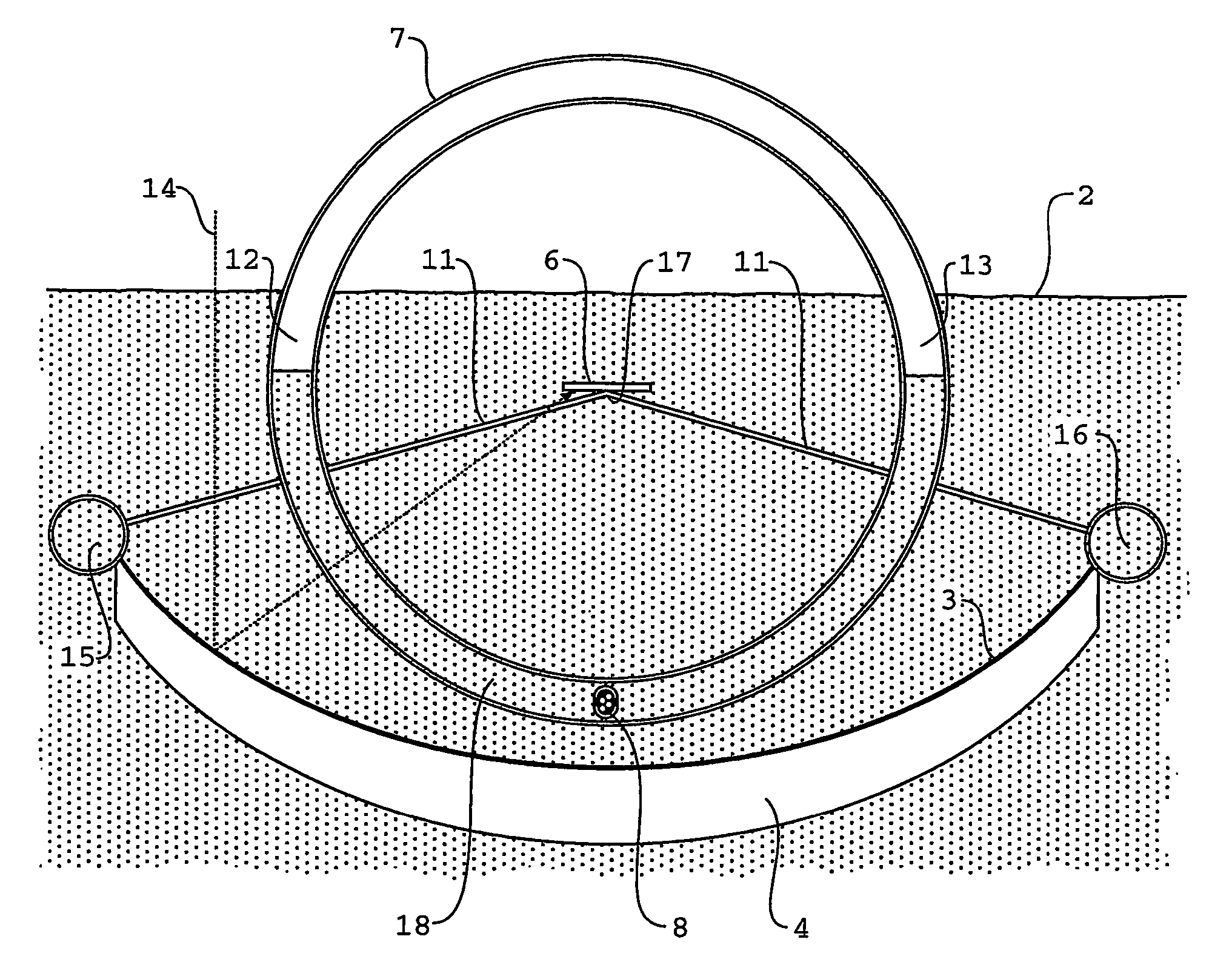
[0035]According to the embodiment of the present invention which is illustrated by reference to FIG. 1, a plurality of assemblies, one of which is generally indicted by reference numeral 1, are immersed in a pond or other body of transparent liquid 2. It is preferred that the pond of liquid 2 be water.

[0036]The complete immersion of the assembly 1 in the liquid serves to simultaneously protect and cool the apparatus whilst allowing easy rotation about any axis through the center of gravity of the collector. The assembly is given slight positive buoyancy to keep it substantially below the surface, but touching the surface.

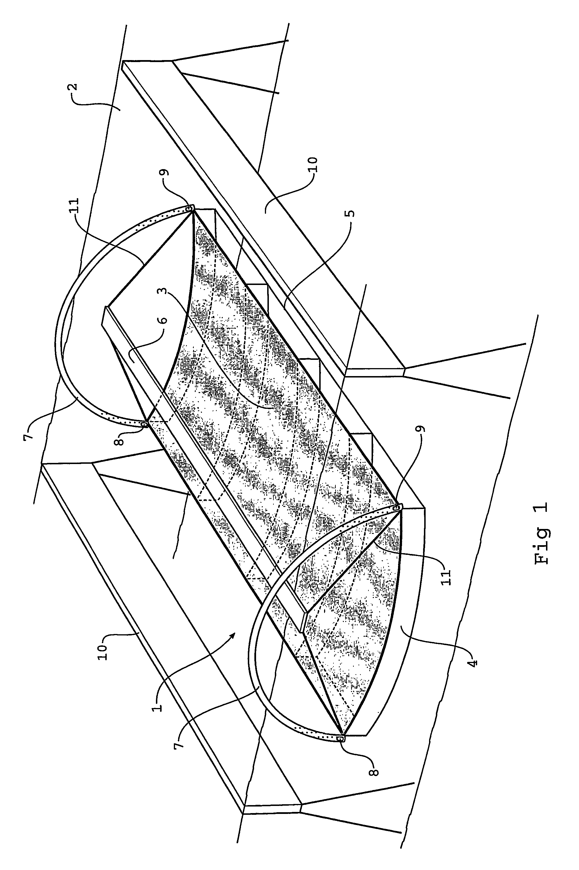
[0037]The solar collector assembly includes a reflector that is generally indicated at 3 (shaded in the diagram). In its preferred form, the reflector 3 has a reflecting surface which is substantially parabolic in a cross-section of the collector, and which extends longitudinally to form a generally trough-shaped reflecting surface.

[0038]Each reflector assembly 3 is...


PUM


Abstract

A solar collector arrangement includes a number of assemblies (1), which are immersed or partially immersed in a pond of water (2). Each assembly (1) includes a parabolic reflector (3) and an absorber (6). Barriers (10) are located on or near the surface of the water (2) and operate to reduce waves which may otherwise disturb the direct passage of sunlight in windy conditions. The complete immersion of the assembly (1) in the liquid serves to simultaneously protect and cool the apparatus, while allowing ease of sun 10 tracking movements by buoyancy induced rotation. Partially immersed versions have higher efficiency and protect against severe weather by inverting into the water.

Description

TECHNICAL FIELD[0001]The present invention relates to the tracking and protection of solar energy collectors and the like.BACKGROUND ART[0002]There is a need to economically collect solar energy in concentrated form prior to direct use or conversion to electricity or other useable forms of energy. Solar energy has a modest intensity at the earth's surface of about 1000 Watts per square meter.[0003]It is thus highly desirable to concentrate the energy to higher intensity (usually expressed in Watts per square meter, or W / m2) before use. This is particularly so where solar cells are used to convert the solar energy into electrical energy. The photovoltaic cells that are used to convert the solar energy into electrical energy are relatively expensive. Concentration of the incident solar energy into a smaller area allows the use of a smaller area of energy conversion cells, with lower resulting costs of conversion cells. The key requirement in a concentrating collector is a means to con...

Claims


Application Information

Patent Timeline
Patent Type & Authority Patents(United States)
IPC IPC(8): F24J2/12H02N6/00F24J2/52F24S23/30F24S23/71F24S23/74F24S23/79F24S50/20F24S90/00H01L31/052
CPCF24J2/085F24J2/12F24J2/14F24J2/18F24J2/38F24J2/5269H01L31/0521H01L31/0547Y02E10/43Y02E10/45Y02E10/47Y02E10/52Y02E10/42F24S23/71F24S23/74F24S50/20F24S23/79F24S23/31F24S20/70F24S30/422F24S30/452H01L31/00Y02E10/40
Inventor CONNOR, PHILIP MICHAEL
Owner SUNENGY PTY LTD
Why Eureka
Try Eureka