Eureka AIR delivers breakthrough ideas for toughest innovation challenges, trusted by R&D personnel around the world.

Device and method for generating an adjustable chaotic signal

a technology of chaotic signal and device, applied in the direction of generating/distributing signals, instruments, pulse techniques, etc., can solve the problems of high power consumption, inability to use frequency division multiplexing (fdm) methods, chaotic signal generated by such chaotic signal generation devices, etc., and achieve the effect of reducing power consumption

Active Publication Date: 2010-01-05
SAMSUNG ELECTRONICS CO LTD
View PDF1 Cites 5 Cited by
  • Summary
  • Abstract
  • Description
  • Claims
  • Application Information

AI Technical Summary

Benefits of technology

[0012]An aspect of the present invention is to provide a device and method for generating an adjustable chaotic signal so as to reduce power consumption and to be capable of adjusting the center frequency and bandwidth for spontaneous wireless communication by a plurality of users.
[0021]The higher the DC bias value applied by the DC bias controller is, the higher the center frequency of the chaotic signal is.

Problems solved by technology

However, the chaotic signal generated by such chaotic signal generation devices is a single signal in the entire frequency band of a UWB.
Thus, if a plurality of users use wireless devices in a particular wireless communications area, utilization of the same channel results in interference.
That is, it is impossible to use a frequency division multiplexing (FDM) method in which a plurality of users carry out communications using a plurality of frequency channels in a particular communications area.
Moreover, as a chaotic signal is generated in the entire frequency band of a UWB and requires high non-linearity of a power amplifier, power consumption is high.

Method used


Image

  • Device and method for generating an adjustable chaotic signal
  • Device and method for generating an adjustable chaotic signal
  • Device and method for generating an adjustable chaotic signal

Examples


Embodiment Construction

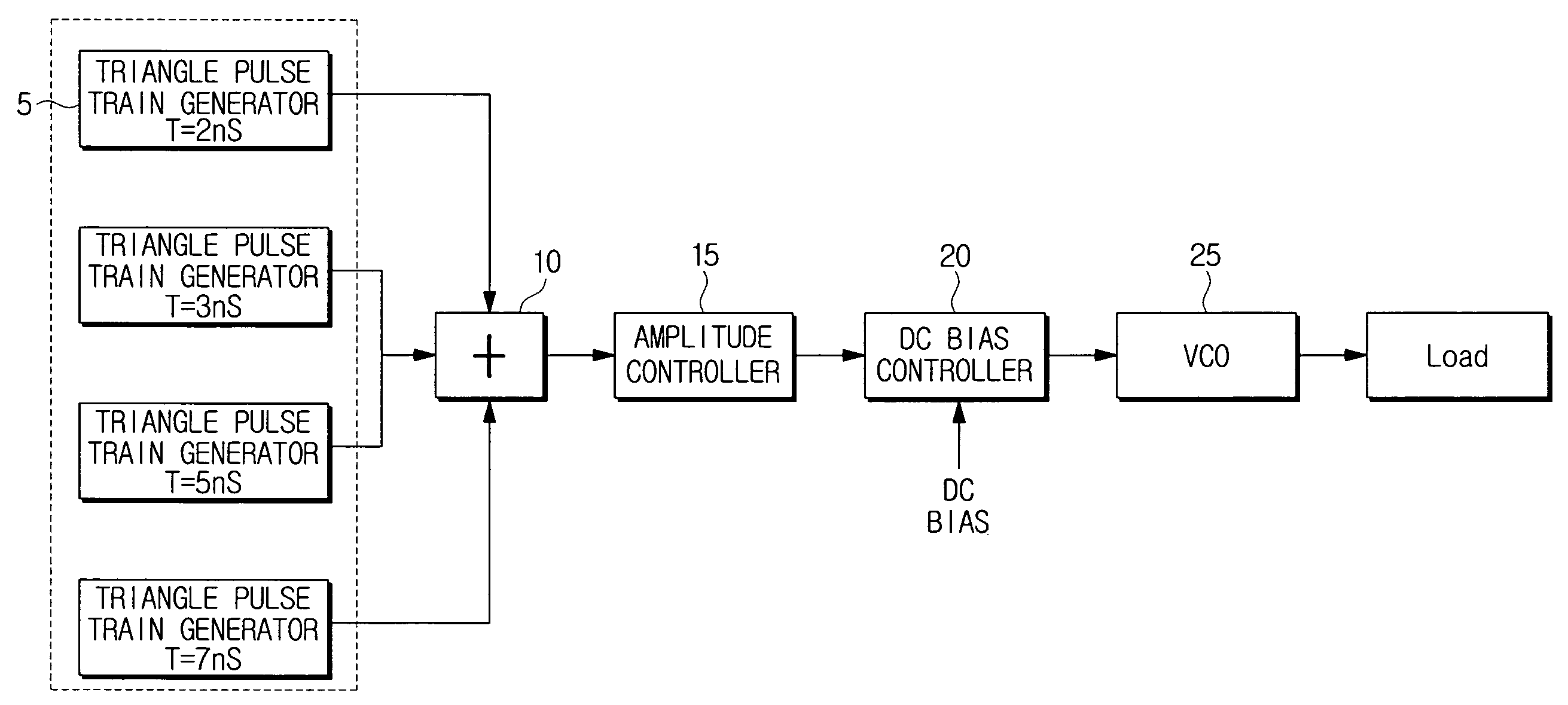
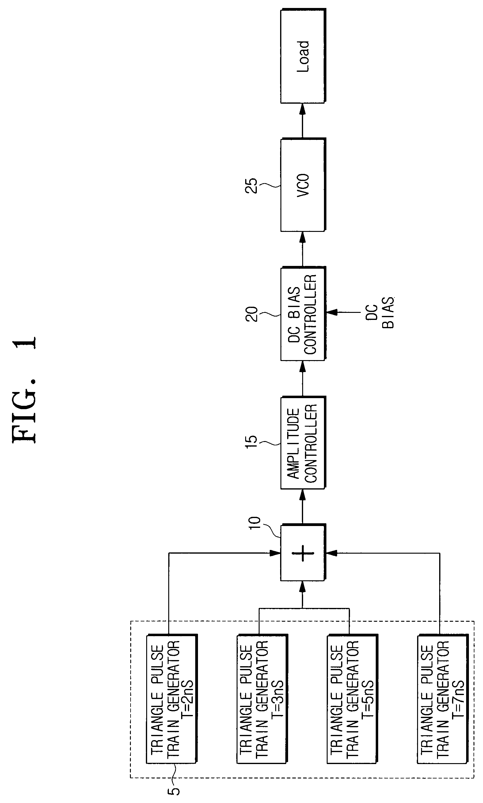
[0033]Hereinafter, exemplary embodiments of the present invention will be described in detail with reference to the accompanying drawing figures.

[0034]In the following description, the same drawing reference numerals are used for the same elements even in different drawings. The matters defined in the description such as a detailed construction and elements are nothing but the ones provided to assist in a comprehensive understanding of the invention. Thus, it is apparent that the present invention can be carried out without those defined matters. Also, well-known functions or constructions are not described in detail since they would obscure the invention in unnecessary detail.

[0035]FIG. 1 is a block diagram illustrating the configuration of a chaotic signal generation device for UWB communications according to an exemplary embodiment of the present invention.

[0036]The chaotic signal generation device 1 generates a chaotic signal in a desired frequency band, and comprises a pluralit...


PUM


Abstract

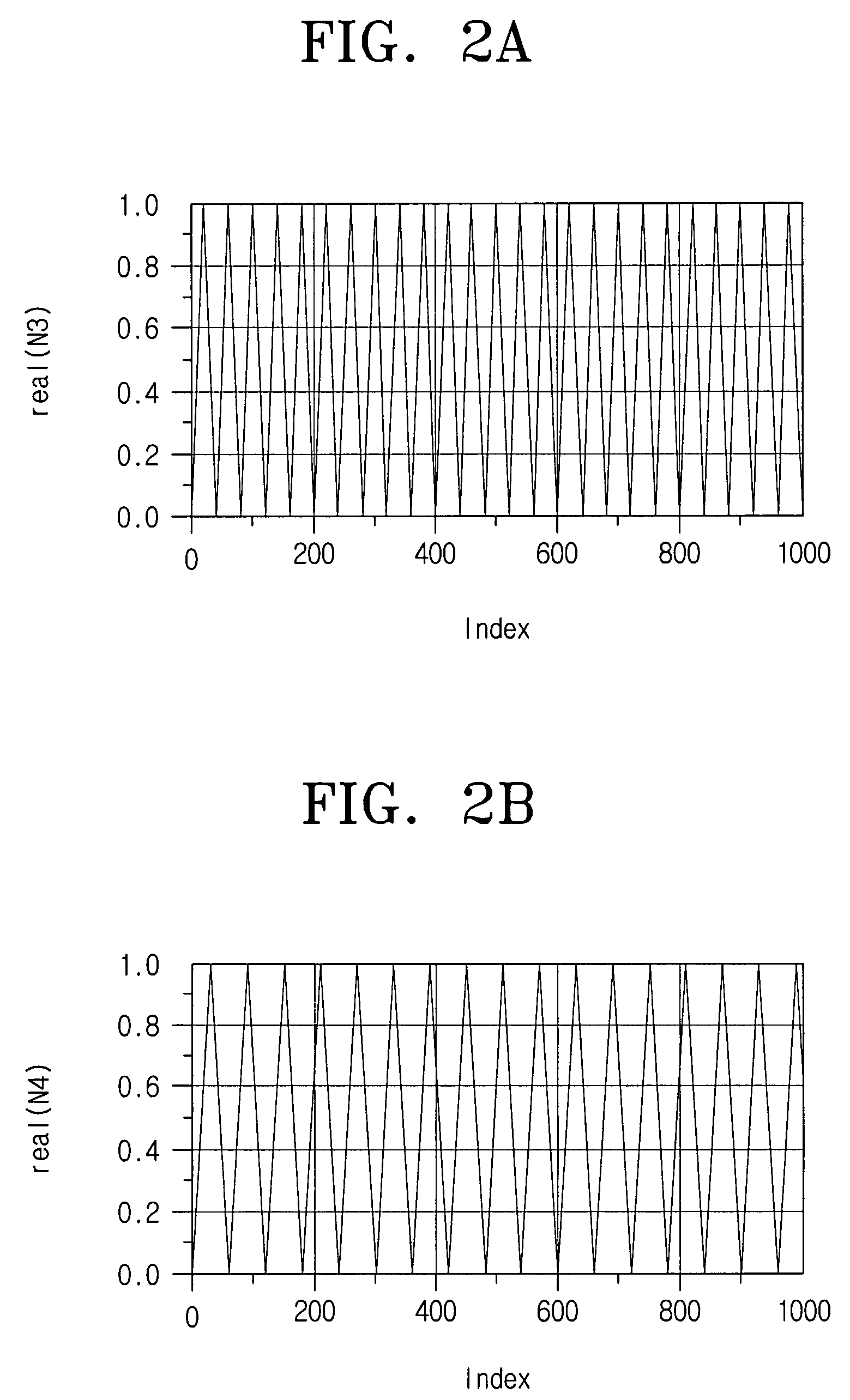
A device and method for generating an adjustable chaotic signal are provided. The chaotic signal generation device includes a plurality of triangle pulse train generators which generate a plurality of triangle waves having different frequency cycles, an adder which adds the triangle waves output from the triangle pulse train generators and outputs a noise signal, and a frequency modulator which converts the noise signal to a certain frequency band to output a chaotic signal. Accordingly, the power consumption and cost are reduced and the manufacture of the chaotic signal generation device is simplified due to the components integrated on an IC. Also, a plurality of users can use wireless communications in a particular wireless communications area.

Description

CROSS-REFERENCE TO RELATED APPLICATIONS[0001]This application priority from Russian Patent Application No. RU2006120279, filed Jun. 9, 2006, in the Russian Patent Office, and the Korean Patent Application No. 2006-125379, filed Dec. 11, 2006, in the Korean Intellectual Property Office, the entire contents of which are incorporated herein by reference.BACKGROUND OF THE INVENTION[0002]1. Field of the Invention[0003]Apparatuses and methods consistent with the present invention relate to generating an adjustable chaotic signal, and more particularly, to generating an adjustable chaotic signal so as to reduce power consumption and to be capable of adjusting the center frequency and bandwidth.[0004]2. Description of the Related Art[0005]Recently, wireless communications methods using an ultra wideband (UWB) frequency band in a spectrum of 3.1 GHz to 5.1 GHz other than Bluetooth have developed, among which is a method for transmitting information using a chaotic signal proposed by the IEEE...

Claims


Application Information

Patent Timeline
Patent Type & Authority Patents(United States)
IPC IPC(8): H03B29/00
CPCH04B1/7172H04B1/719H04L27/001
Inventor HAN, SANG-MINPOPOV, OLEG
Owner SAMSUNG ELECTRONICS CO LTD
Why Eureka
Eureka Blog
Learn More