Perpendicular magnetic recording head for high frequency drive
a magnetic recording head and high frequency technology, applied in the field of magnetic recording heads, can solve the problems of inability to precisely record aimed magnetic information, record operation, etc., and achieve the effects of excellent high frequency characteristics, narrow track width, and high capacity
- Summary
- Abstract
- Description
- Claims
- Application Information
AI Technical Summary
Benefits of technology
Problems solved by technology
Method used
Image
Examples
embodiment 1
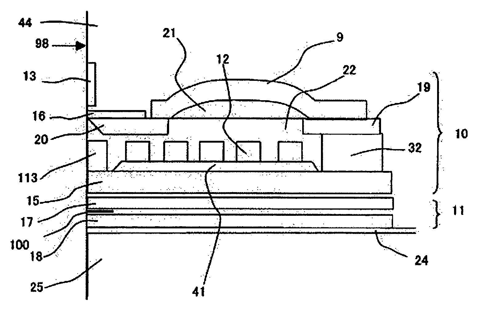
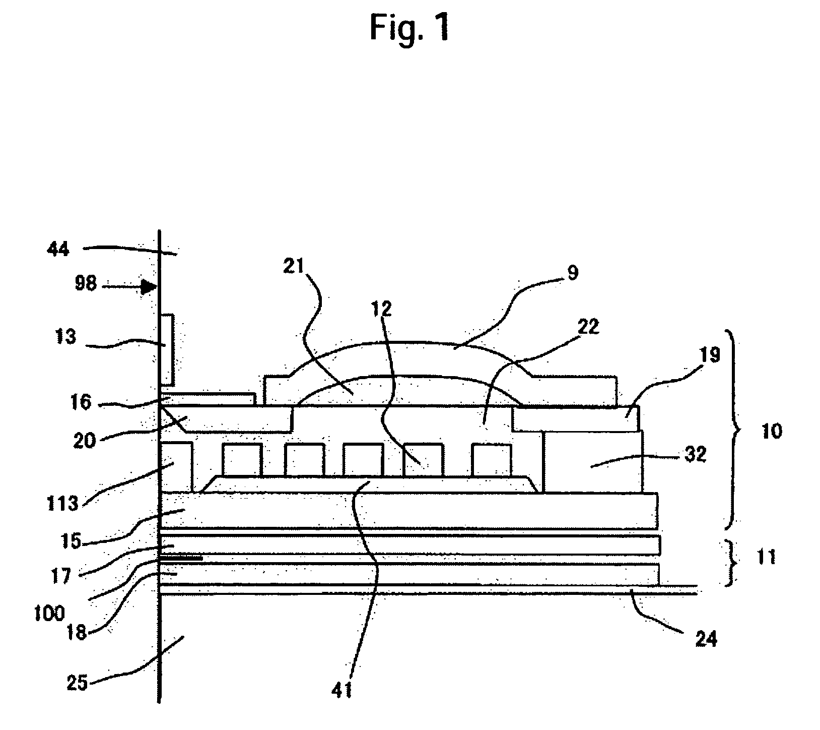
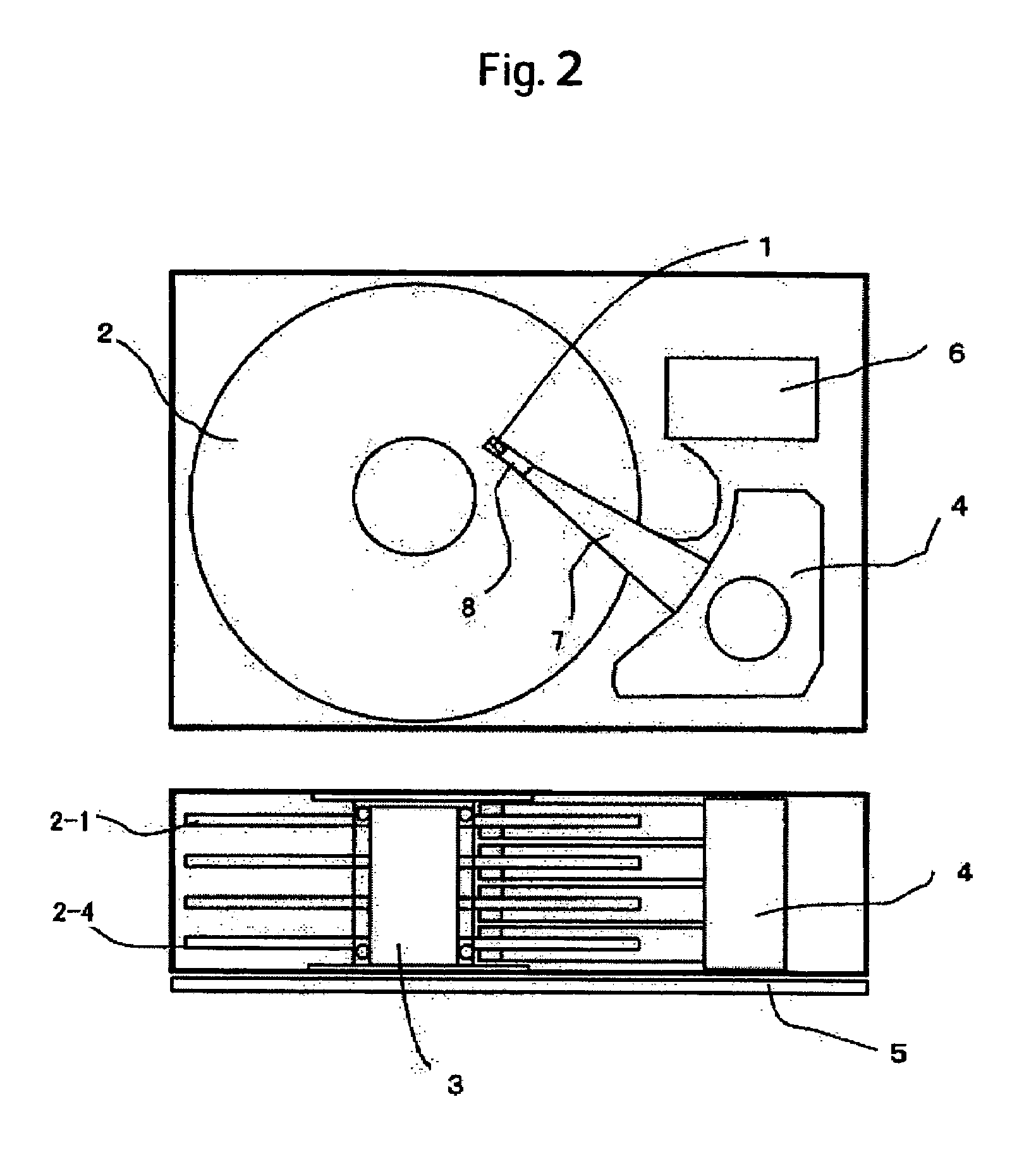
[0044]A description will be made of a structure of an information write function portion and an information read function portion mounted on the magnetic head 1. FIG. 1 is a cross sectional view of a device taken along a plane passing through the center of a main magnetic pole piece 16 and extending vertical to an air bearing surface 98. FIGS. 3 and 4 are views as viewed from the air bearing surface 98 and from the trailing side, respectively. FIG. 1 shows a structure in which a read function portion 11 and a write function portion 10 are stacked by way of a non-magnetic film over a substrate 25 of a slider.
[0045]The read function portion 11 comprises a lower shield 18, an upper shield 17 and, further, a magnetoresistive element 100 surrounded by the upper and lower shields and exposed in part to the air bearing surface. The magnetoresistive element 100 is connected to an electrode and has a function of transmitting electric information from the read function portion to the signal p...
embodiment 2
[0079]Embodiment 2 is a modified example of a structure in which the fourth magnetic film 20 in Embodiment 1 is not exposed to the air bearing surface.
[0080]FIG. 8 is a cross sectional view illustrating the constitution in which a fourth magnetic film 201 is spaced from the air bearing surface. FIG. 9 illustrates a positional relationship between a main magnetic pole piece 16 and a fourth magnetic film 201 adapted to magnetically connect a curved first magnetic film 9 and the main magnetic pole piece 16, the left figure being as viewed from the air bearing surface side and the right figure being as viewed from the trailing side. Additionally, FIG. 9 shows a relationship between the main magnetic pole piece 16 and the fourth magnetic film 201 therebelow in the widthwise-corresponding manner as viewed from the air bearing surface (on the right) and as viewed from the trailing side (on the left). While the function of the fourth magnetic film 201 has been described in Embodiment 1, a c...
embodiment 3
[0083]This embodiment shows a modified example of the curved portion of the first magnetic film 9 in Embodiment 1. As a mechanism for directing the magnetic domains formed in the first magnetic film in parallel with the track width, the curved surface may be left at least on one side of the first soft magnetic film as shown in FIG. 11.
[0084]In FIG. 11, a curved surface is formed on one side of a soft magnetic film pattern 93 as a first magnetic film and a planar surface 931 is formed on the other (upper) side of the pattern 93. The first magnetic film 93 is in contact with the non-magnetic material 21 and the curvature is provided for the contact surface of the non-magnetic body 21, thereby forming the curved portion on the lower surface of the first magnetic film 93. The non-magnetic body 21 is constituted with a polymeric resin and subjected to a heat treatment.
[0085]If a shape of generating magnetic charges at a film surface is artificially prepared in a case where magnetic domai...
PUM
| Property | Measurement | Unit |
|---|---|---|
| frequency | aaaaa | aaaaa |
| resistivity | aaaaa | aaaaa |
| size | aaaaa | aaaaa |
Abstract
Description
Claims
Application Information
 - R&D
- Intellectual Property
- Life Sciences
- Materials
- Tech Scout
- Unparalleled Data Quality
- Higher Quality Content
- 60% Fewer Hallucinations
Browse by: Latest US Patents, China's latest patents, Technical Efficacy Thesaurus, Application Domain, Technology Topic, Popular Technical Reports.
© 2025 PatSnap. All rights reserved.Legal|Privacy policy|Modern Slavery Act Transparency Statement|Sitemap|About US| Contact US: help@patsnap.com


