Image processing system for volume rendering

a volume rendering and image processing technology, applied in tomography, multi-programming arrangements, instruments, etc., can solve the problems of reducing system efficiency, difficult to predict the end time, and limiting the total computation performed by the computer resource, so as to shorten the processing time of volume rendering

Inactive Publication Date: 2010-01-12
ZIOSOFT
View PDF8 Cites 18 Cited by
  • Summary
  • Abstract
  • Description
  • Claims
  • Application Information

AI Technical Summary

Benefits of technology

[0020]This invention has been achieved to solve above-mentioned problems, and it is an object of the invention to provide a volume rendering image processing system which shortens processing time of volume rendering by making effective use of a plurality of CPU resources within a network without need of predicting the end time.
[0023]Also, because an execution request of the job is made without considering the actual load factor of the node and the processing capability on the job accepting side, it is possible to avoid the overhead of the computer on the job requesting side.
[0025]With this constitution, the node of slow processing can be stopped to perform the processing in the course of processing without waiting to receive the processing result of the job from the node that has completed the processing the earliest, whereby the wasteful process of computer resources are not continued and the volume rendering processing is performed more efficiently.
[0039]With this constitution, the image processing at the final step is not usually a very heavy load, and the image is finally displayed on the display of the user console, whereby the processing results of the nodes are unified sooner or later. The operability of the user is made better if they are unified in good time.

Problems solved by technology

However, in the volume rendering which requires a large amount of computation at high precision and in real time, there is a limit if the total computation is performed by the computer resource of one computer.
Generally, its management is very difficult, and may cause an overhead, which lowers the system efficiency in the worst case.
Particularly, even though the load information and resource use situation of the plurality of computers are collected beforehand to assign the jobs fairly, it is not easy to predict the end time.

Method used


Image

  • Image processing system for volume rendering
  • Image processing system for volume rendering
  • Image processing system for volume rendering

Examples


Embodiment Construction

[0050]The best mode for carrying out the present invention will be described below with reference to the accompanying drawings.

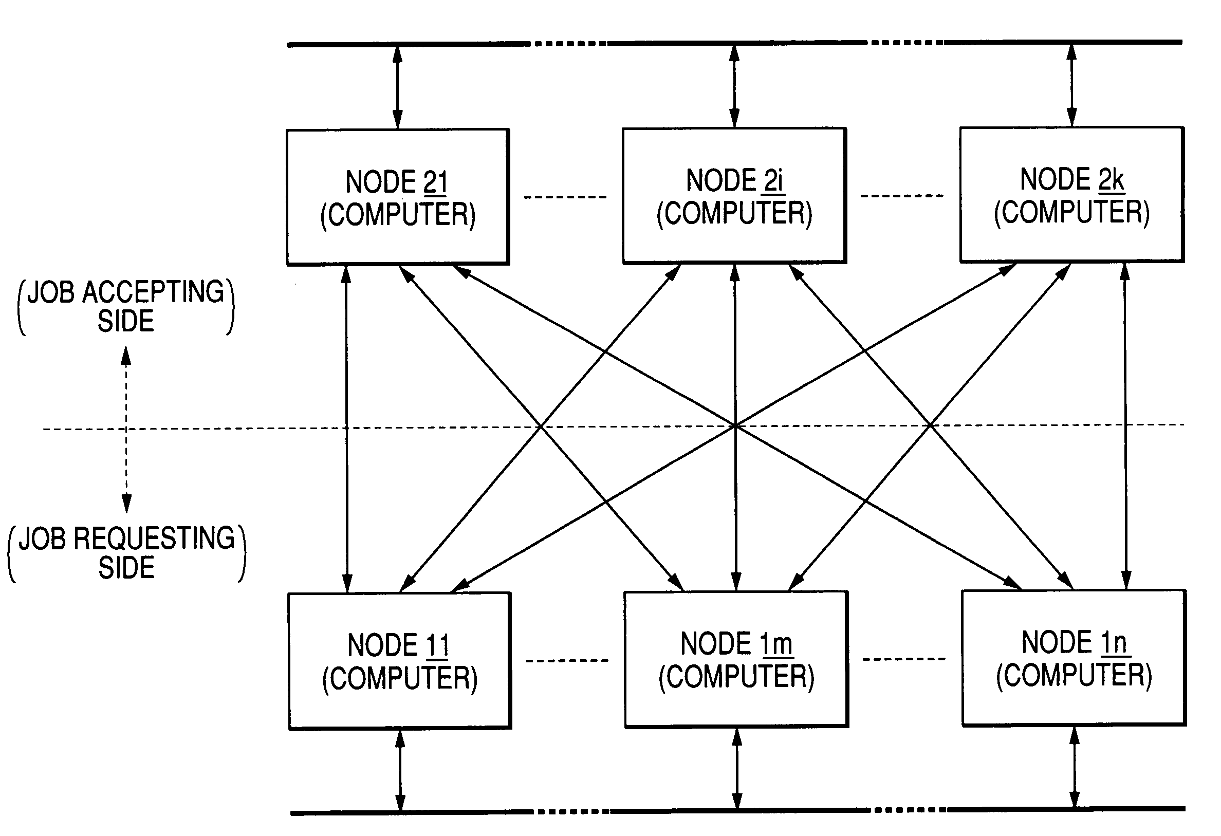
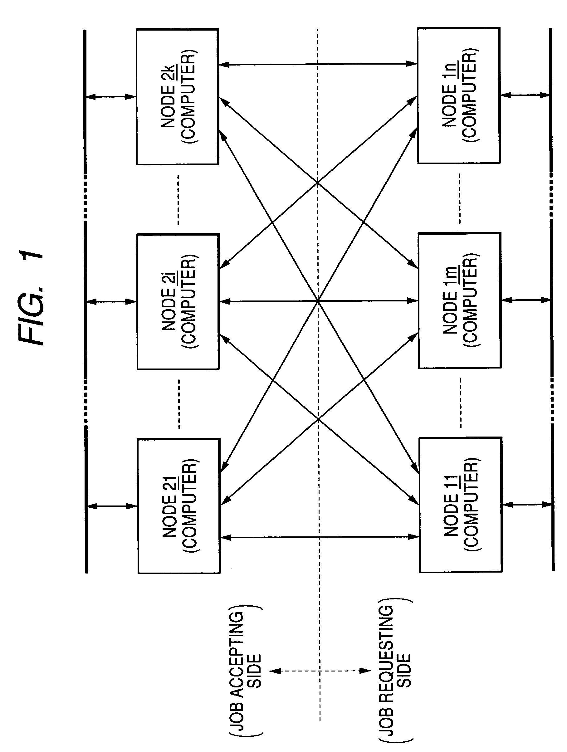
[0051]FIG. 1 is a block diagram showing a network configuration of a volume rendering image processing system according to one embodiment of the invention.

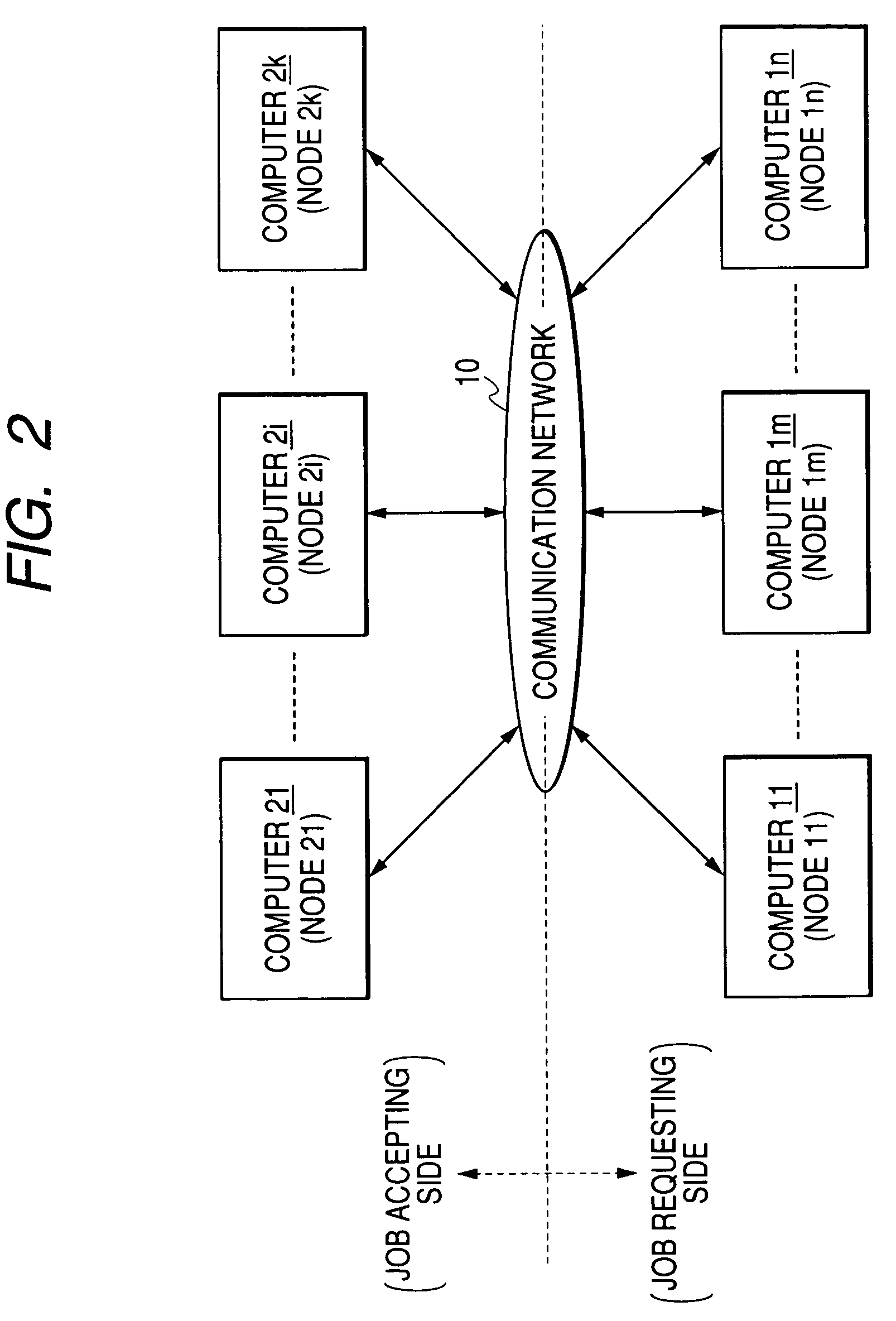
[0052]As shown in FIG. 1, the network configuration of the volume rendering image processing system according to the embodiment comprises the nodes 11 to in on the job requesting side in which a volume rendering processing is segmented into jobs, and the nodes 21 to 2k on the job accepting side. Each of the nodes is connected to a network and communicable with other nodes via the network. The term “node” as used herein means a computer as a computing unit, and a supercomputer containing a plurality of CPUs, a server, a personal computer, and a notebook personal computer may respectively be all one nodes.

[0053]The nodes 11 to in are in the equivalent relation with each other. Also, the nodes 21 to 2k are in...


PUM


Abstract

A CPU 111m segments the jobs from each of the volume rendering processing on hand, prioritize processing sequence for each job, transmits one job which has reached the processing order to the computers (21 to 2k) on the accepting side and other computers equivalent to the self computer simultaneously, and executes the job for self processing. Then, after if receiving the processing result from the computer which has completed the processing of the transmitted job the earliest, the CPU 111m issues a halt command of the job to other computers on the accepting side. At this time, if any job to be requested on hand remains uncompleted, a series of processing procedures starting with the simultaneous communication is repeated.

Description

[0001]This application claims foreign priority based on Japanese Patent application No. 2004-154261, filed May 25, 2004, the contents of which is incorporated herein by reference in its entirety.BACKGROUND OF THE INVENTION[0002]1. Field of the Invention[0003]The present invention relates to an image processing system for volume rendering, and more particularly to an image processing system for performing a volume rendering image processing or a region segmentation processing, using a plurality of computers connected via a network.[0004]2. Description of the Related Art[0005]With the development of an image processing technique using the computer, the appearance of CT (Computed Tomography) scanner and MRI (Magnetic Resonance Imaging) that enables an internal structure of the human body to be directly observed has brought about innovation in the medical field. A medical diagnosis using a tomographic image of the living body has been widely performed. In recent years, as a technique fo...

Claims


Application Information

Patent Timeline
Patent Type & Authority Patents(United States)
IPC IPC(8): G06F9/46A61B6/03G06F15/16G06T1/00G06T1/20H04L29/08
CPCH04L67/1008H04L67/1036H04L67/1002H04L67/1012H04L67/1001
Inventor MATSUMOTO, KAZUHIKO
Owner ZIOSOFT
Why Eureka
Try Eureka