Vertical internal combustion engine provided with belt-drive transmission mechanism

a technology of internal combustion engine and transmission mechanism, which is applied in the direction of valve drive, machine/engine, lubrication of auxillaries, etc., can solve the problems of belts being likely to be exposed to gas containing oil mist and blowby gases, excessive lubrication of belts, and degradation of rubber belts, etc., to achieve small breather chambers, low oil separation ability of breather chambers included in breather structures, and good lubrication

Inactive Publication Date: 2010-01-19
HONDA MOTOR CO LTD
View PDF17 Cites 9 Cited by
  • Summary
  • Abstract
  • Description
  • Claims
  • Application Information

AI Technical Summary

Benefits of technology

[0007]The present invention has been made under such circumstances and it is therefore an object of the present invention to extend the life of the rubber belt of the belt-drive transmission mechanism included the vertical internal combustion engine by preventing excessive contact between the rubber belt and the oil-containing gas from the crankcase and to ensure that the rubber belt is properly lubricated.
[0009]According to the present invention, the belt chamber is isolated from the crankcase such that the oil-containing gas flowing from the crankcase chamber into the belt chamber flows in a direction deviating from a direction toward the belt. Consequently, less oil-containing gas, as compared with oil-containing gas that comes into contact with the belt when the oil-containing gas flows toward the belt, touches the belt and hence the degradation of the belt resulting from contact with the oil and blowby gases contained in the oil-containing gas can be suppressed. Therefore, the lubrication of the belt with the oil can extend the life of the belt and maintenance interval. The lubricating means supplies the oil for lubricating the belt concentratedly to a limited range in the belt. Whereas the belt lubricated with the oil contained in the oil-containing gas is always entirely wetted with the oil, the belt lubricated by the lubricating means can be lubricated by a measured quantity of the oil or a desired part of the belt can be wetted with the oil. Thus the belt can be properly lubricated.
[0011]The belt is lubricated with the oil spouted through the jet nozzles disposed in the belt chamber, the amount of the oil to be discharged onto the belt and a part of the belt to be wetted with the oil discharged through the jet nozzles can be easily determined and hence the belt can be properly lubricated.
[0013]Since the belt is lubricated with the oil dropped through the oil holes formed in the intermediate wall, a part of the belt to be wetted with the oil dripped through the oil holes can be easily determined and hence the belt can be properly lubricated. Since the oil for lubricating the belt is extracted from the oil-containing gas, the oil separating ability of a breather chamber included in a breather structure may be low and hence the breather chamber may be small.

Problems solved by technology

If the belt chamber is opened into the crankcase and the components of the belt-drive transmission mechanism including a belt and pulleys are exposed to the atmosphere in the crankcase, the belt is likely to be exposed to gas containing oil mist and blowby gases.
Moreover, the belt is wetted with oil drops splashed by the rotating crankshaft and with the oil adhered to the pulleys and scattered when the pulleys rotate.
Consequently, the belt is excessively lubricated.
If the belt is exposed excessively to the oil and blowby gases contained in the oil-containing gas and to the high-temperature oil-containing gas, components of the oil and the blowby gases accelerate the degradation of the rubber belt and shorten the life of the rubber belt.
If the width and thickness of the belt is increased and the strength of the belt is enhanced to reduce the detrimental effect of degradation on the belt, the cost and size of the belt-drive transmission mechanism increase.
If the belt is not satisfactorily lubricated, the belt is abraded by increased friction between the belt and the pulley and the life of the belt shortens.
Thus it is difficult to suppress the degradation of the belt by detrimental effects of the oil and blowby gases contained in the oil-containing gas and to ensure the proper lubrication of the belt when the belt is lubricated with the oil contained in the oil-containing gas from the crankcase.

Method used


Image

  • Vertical internal combustion engine provided with belt-drive transmission mechanism
  • Vertical internal combustion engine provided with belt-drive transmission mechanism
  • Vertical internal combustion engine provided with belt-drive transmission mechanism

Examples


first embodiment

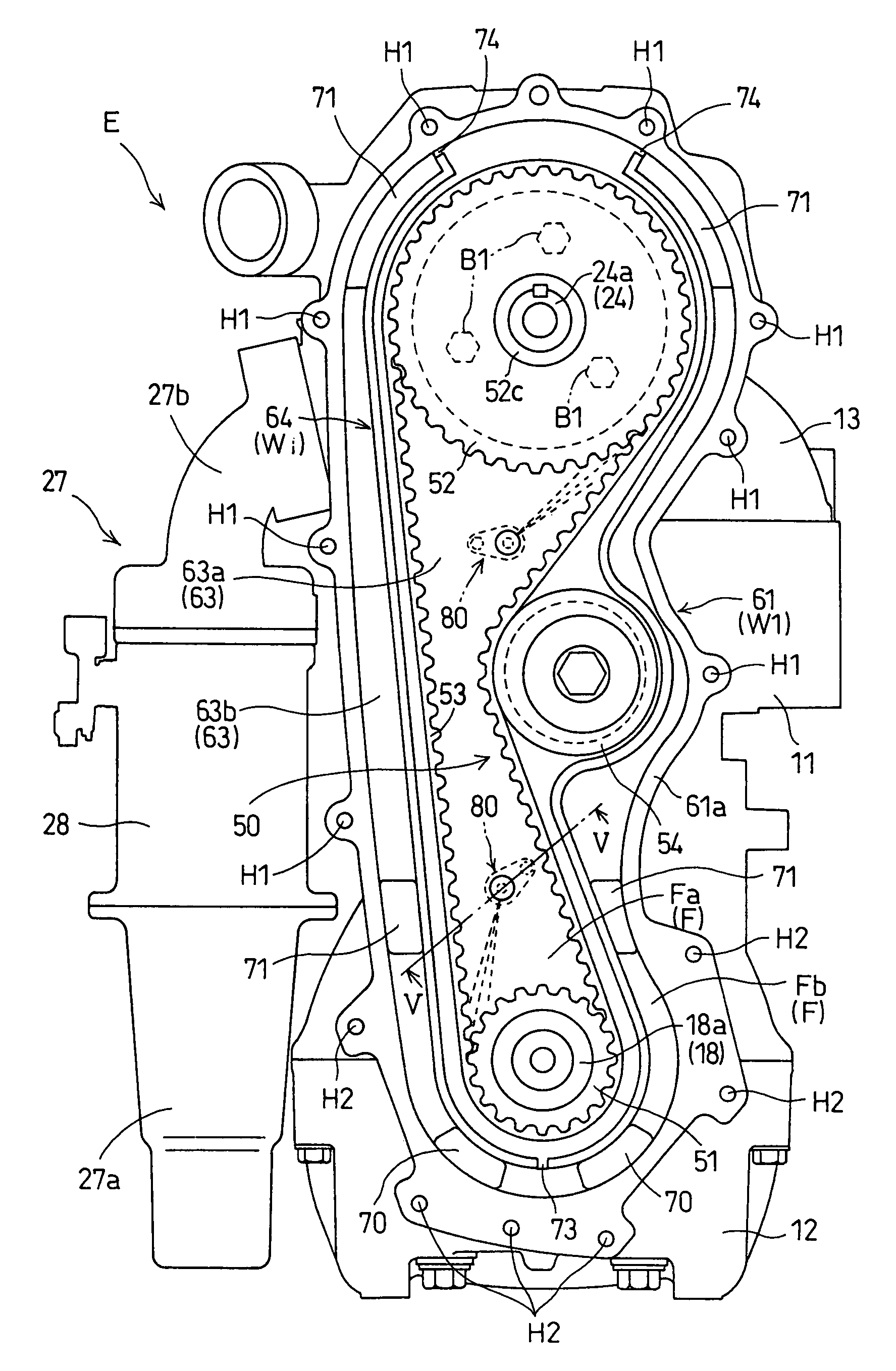
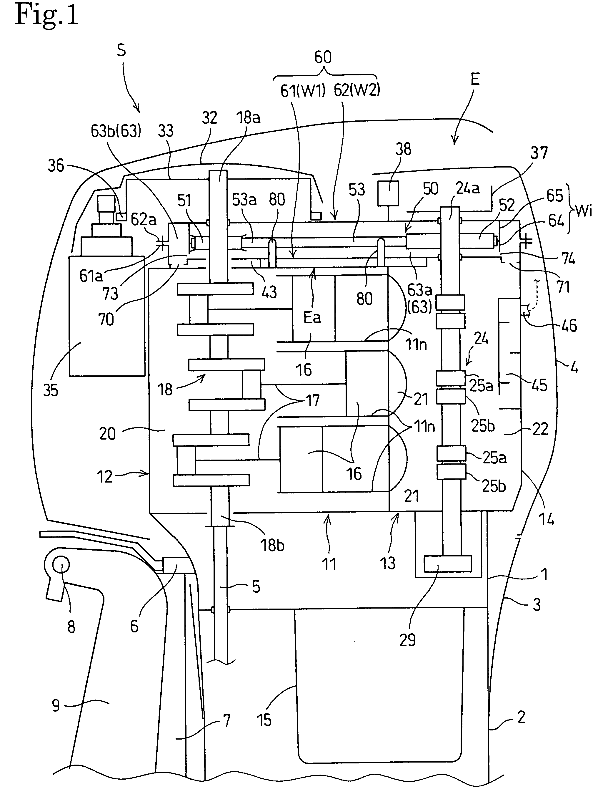
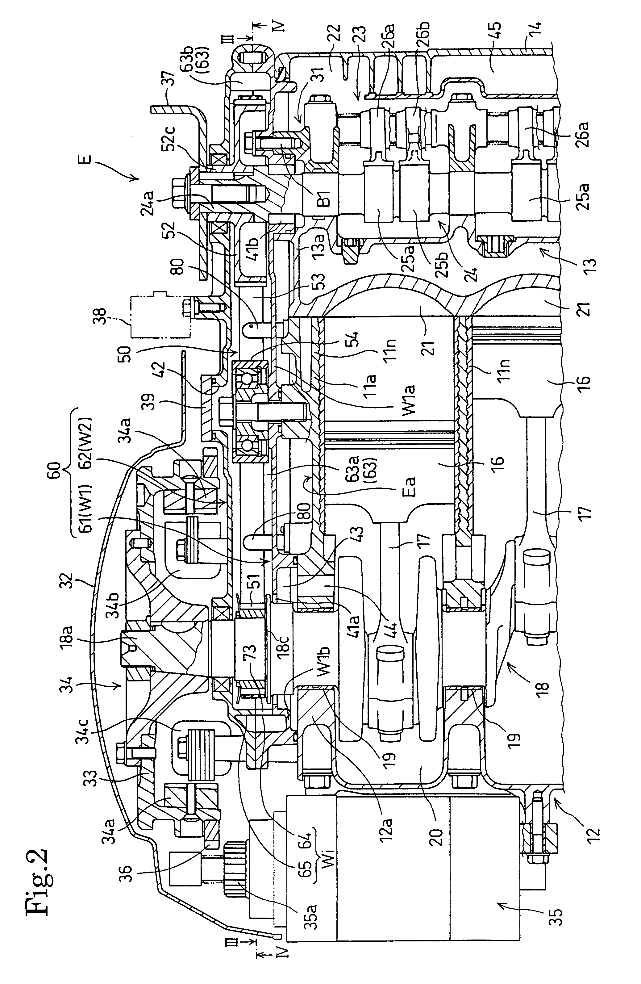
[0022]FIGS. 1 to 5 illustrate a vertical internal combustion engine E in the present invention.

[0023]Referring to FIG. 1, the vertical internal combustion engine E is incorporated into an outboard motor S. The outboard motor S includes the internal combustion engine E disposed with the center axis of its crankshaft 18 vertically extended, a mount case 1 supporting the internal combustion engine E, an extension case 2 joined to the lower end of the mount case 1, a gear case joined to the lower end of the extension case 2, an under cover 3 covering a part between a lower part of the internal combustion engine E and an upper part of the extension case 2, and an engine cover 4 joined to the upper end of the under cover 3.

[0024]The outboard motor S has a transmission mechanism including a drive shaft 5 coaxially connected to a lower end part 18b of the crankshaft 18, a reversing mechanism held in the gear case, and a propeller. The power of the internal combustion engine E is transmitted...


PUM


Abstract

A vertical internal combustion engine E is incorporated into an outboard motor or the like. The vertical internal combustion engine E includes a crankshaft 18 enclosed in a crank chamber 20, and a belt-drive transmission mechanism 50 including a rubber belt 53 for transmitting power of the crankshaft 18 to a camshaft 24, and held in a belt chamber 63. The belt chamber 63 is isolated from the crank chamber 20 by a lower case 61 of a transmission case 60 holding the belt-drive transmission mechanism 50 therein such that the flow of an oil-containing gas from the crank chamber 20 deviates from a direction toward the belt 53. The belt 53 is lubricated with oil injected concentratedly into the belt chamber 63 through jet nozzles 80 disposed in the belt chamber 63. Thus the excessive exposure of the belt 53 to the oil-containing gas from the crank chamber can be avoided, the life of the belt can be extended and the belt is lubricated properly.

Description

BACKGROUND OF THE INVENTION[0001]1. Field of the Invention[0002]The present invention relates to a vertical internal combustion engine having a crankshaft held in a crankcase with its center axis vertically extended, and provided with a belt-drive transmission mechanism including a lubricated rubber belt for transmitting the power of the crankshaft to a driven device. The vertical internal combustion engine is incorporated into, for example, an outboard motor.[0003]2. Description of the Related Art[0004]A vertical internal combustion engine disclosed in, for example, JP-A 2-275020 is provided with a belt-drive transmission mechanism including a rubber belt for transmitting the power of the crankshaft to a driven device. The belt-drive transmission mechanism is placed in a belt chamber, and the rubber belt is lubricated with oil that flows from the crankcase into the belt chamber.[0005]If the belt chamber is opened into the crankcase and the components of the belt-drive transmission ...

Claims


Application Information

Patent Timeline
Patent Type & Authority Patents(United States)
IPC IPC(8): F01L1/02
CPCF01L1/02F01L1/024F01L1/053F02B61/045F02B67/06F02B75/007
Inventor TAKADA, HIDEAKIKUBOTA, YUTAKAKURODA, TATSUYAKOYAMA, KAZUTAKE
Owner HONDA MOTOR CO LTD
Why Eureka
Try Eureka